Abstract
This document describes the usage and configuration of the wiFred - a very simple wireless throttle for model railroads to connect to wiThrottle servers like JMRI. It also contains schematics and BOMs for the device - for both LiPo battery versions in active development - as well as programming instructions and assembly tips, and also an overview of options for the server side of things.
The most recent version of this document can be found at https://newheiko.github.io/wiFred, https://github.com/newHeiko/wiFred/raw/master/documentation/docu_en.pdf and https://github.com/newHeiko/wiFred/blob/master/documentation/docu_en.adoc.
If you want to know more about the development history of the wiFred, skip ahead to Background for wiFred development - otherwise read on with Quickstart Guide.
Quickstart Guide
First startup
-
Charge device with a micro USB charger until charging LED switches to green
-
Turn on device with charger still connected (calibrates low battery threshold)
-
Wait for red LED on top to stop flashing and stay lit
-
Use any WiFi device to search for and connect to network wiFred-configXXXX
-
Connect to http://config.local and configure device
More information can be found at https://newHeiko.github.io/wiFred.
Usage
Operating locos
| Red LED | Green LED (Left) | Green LED (Right) | Status |
|---|---|---|---|
Slow Blinking (0.5 Hz) |
Off |
Off |
Trying to connect to WiFi network |
Fast Blinking (2 Hz) |
Off |
Off |
Successful WiFi connection, trying to connect to wiThrottle server and acquire locos |
Off |
Off |
On |
Regular operation, forward direction |
Off |
On |
Off |
Regular operation, reverse direction |
Off |
Flashing |
On |
Emergency stop, forward direction. Also happens when switching direction with speed potentiometer not at zero |
Off |
On |
Flashing |
Emergency stop, reverse direction. Also happens when switching direction with speed potentiometer not at zero |
Off |
Off |
Blinking |
Battery low, regular operation, forward direction |
Off |
Blinking |
Off |
Battery low, regular operation, reverse direction |
Off |
Flashing |
Blinking |
Battery low, Emergency stop, forward direction |
Off |
Blinking |
Flashing |
Battery low, Emergency stop, reverse direction |
Short flashes |
Off |
Off |
Throttle in low-power mode |
Off |
Off |
Off |
Battery empty or no battery inserted |
On |
Off |
Off |
No connection to existing WiFi network. Created internal configuration WiFi network |
Flashing |
Flashing |
Off |
At startup: ESTOP pressed, will reset to factory defaults after five seconds. Release key for normal startup[1] |
Flashing |
Off |
Flashing |
At startup: SHIFT pressed, will open internal configuration WiFi network after five seconds. Release key for normal startup[1] |
Off |
Flashing |
Flashing |
At startup: F0 pressed when connected to WiFi, will not connect to server but enable configuration mode after five seconds. Release key for normal startup[1] |
On |
On |
On |
Configuration mode enabled while connected to existing WiFi network. All locos emergency stop to avoid runaways. Push SHIFT + ESTOP again to exit configuration mode |
To recover from an emergency stop, turn speed potentiometer to zero to re-gain control. |
|||
Also see LED patterns and how they show battery voltage when turning off the wiFred for interpreting the LED patterns when turning off all locos. |
|||
| Red LED | Green LED (Left) | Green LED (Right) | Battery voltage |
|---|---|---|---|
Flashing |
Off |
Off |
Below 3.7V |
On |
Off |
Off |
Between 3.7V and 3.8V |
On |
Flashing |
Off |
Between 3.8V and 3.9V |
On |
On |
Off |
Between 3.9V and 4.0V |
On |
On |
Flashing |
Above 4.0V |
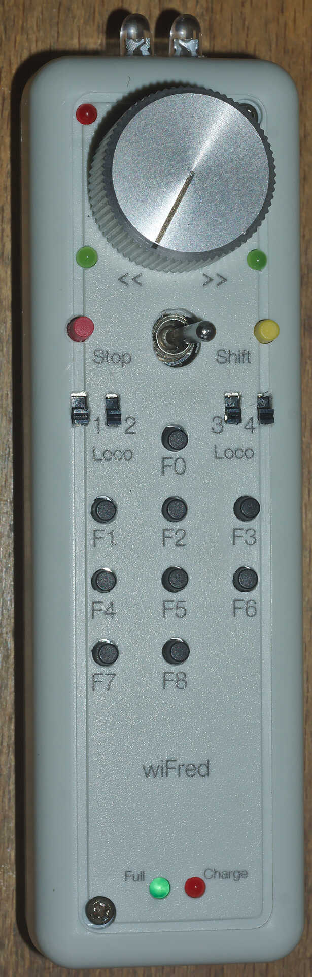
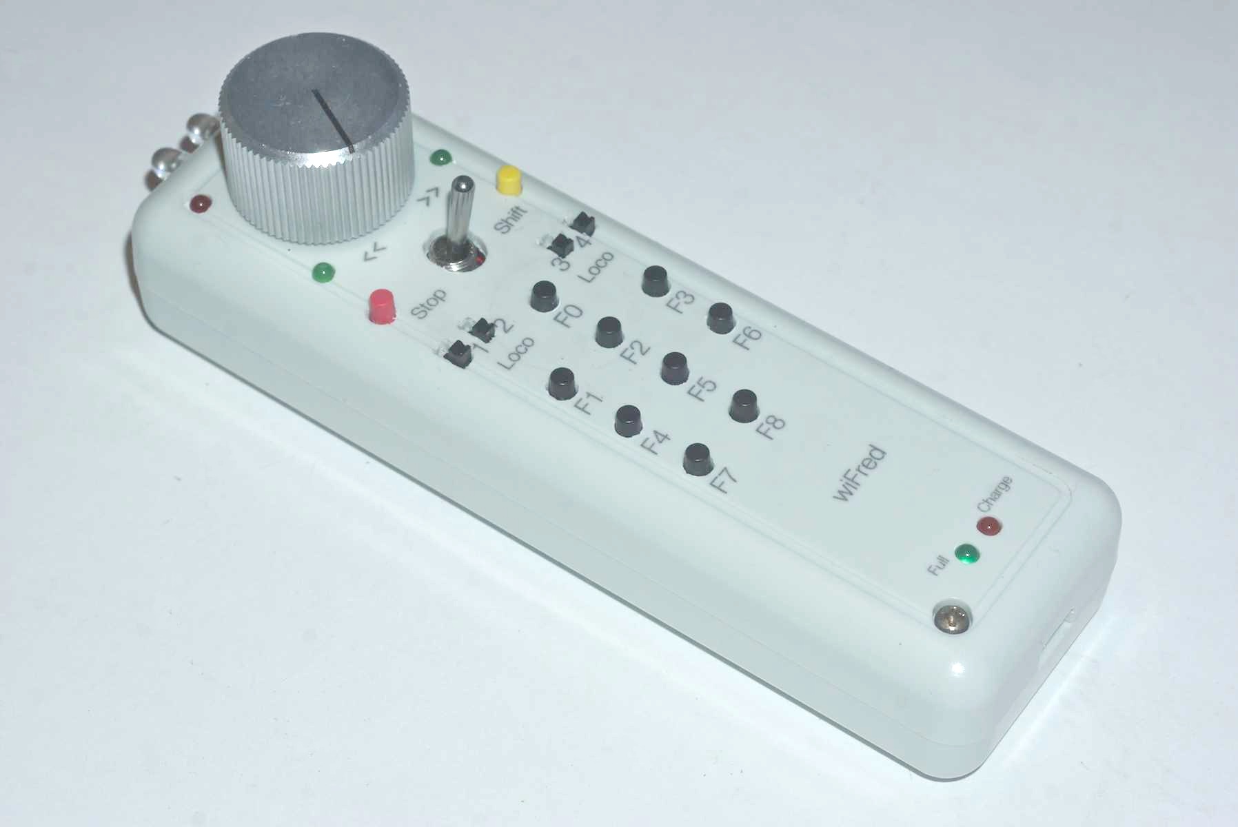
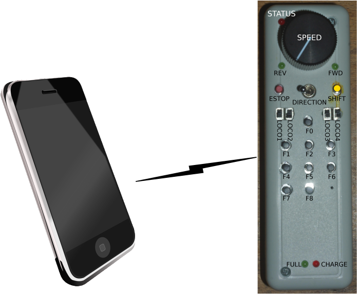
Controls and features of the wiFred throttle shows the controls of the wireless throttle. They consist of the following:
-
Four loco selection switches (loco 1 on the left, loco 4 on the right, move towards speed potentiometer to enable)
-
Speed potentiometer (Counter-clockwise endstop: Stop, clockwise endstop: Full speed)
-
Direction switch - move right for forward movement, left for reverse movement
-
Black function keys F0 to F8
-
Yellow shift key to trigger F9-F16 and turn on flashlight function
-
Red emergency stop key
-
Two green direction indicator LEDs next to speed potentiometer
-
Red status LED next to speed potentiometer
-
Red charging indicator LED at lower end of device - lit while charging
-
Green fully charged indicator LED at lower end of device - lit when fully charged as long as charger still connected
As soon as any of the loco selection switches is moved into the "enabled" position, the throttle will boot up and try to connect to a wireless network. When all four loco selection switches are "disabled", the throttle will disconnect from the wireless network after a grace period of five seconds. The device will then go into low power mode, in which the battery will last for more than a year.
If no connection to the network configured into the device can be established within 60 seconds, the throttle will create it’s own wireless network named wiFred-config plus six hex digits taken from the MAC address of the throttle WiFi interface, for example wiFred-config61FB7B, to enable configuration as described in Configuring the wiFred.
Four different locos with long DCC addresses can be assigned to the four loco selection switches. Commands derived from the speed potentiometer, the direction switch and the function keys will be transmitted to all selected locos (near) simultaneously, with a certain translation table enabling some locos to go backwards when others go forwards and also limiting function keys to some of the four locos only - this is described in more detail in Loco configuration and DCC function configuration.
Pushing the red emergency stop key will cause the throttle to send an emergency stop signal to all four locos attached. After an emergency stop, turn the speed potentiometer to zero to re-enable control of the locos.
Pushing the red emergency stop key while holding down the shift key will place the device into configuration mode (as well as issueing an emergency stop to all attached locos). See Configuring the wiFred for more details on how to access the throttle to do the configuration.
Any change in the loco selection switches will cause the throttle to send an emergency stop command to all attached locos. This makes sure that any loco that is deselected will stop on the layout and avoids newly selected locos suddenly taking off at speed. The same is true for a change in the direction switch, to avoid high-speed reverse maneuvers. Turn the speed potentiometer to zero to re-enable control of the locos.
When the battery is low, the device will not re-activate before charging the batteries, but continue operating for approximately an hour if active. When the battery is empty, it will disconnect and enter low power mode. Expected runtime is around 20 hours of full time operations, more if the throttle is placed in low power mode when the locos are not running.
During startup and operation, the LEDs will show the patterns explained in LED patterns and their meaning on the wiFred. After turning off the wiFred, the LEDs will show the current battery voltage for a few seconds, as described in LED patterns and how they show battery voltage when turning off the wiFred.
Charging the wiFred
The wiFred can be charged through the Micro-USB connector at the lower end of the device. Maximum charging current is approximately 400 mA and the device does not communicate with the USB host, so technically there is no guarantee that charging from a USB cable will work, but most chargers, computer ports or power banks do not check the current before powering up.
As long as the battery is being charged, the red charging indicator LED will be lit. When the battery is fully charged, the green charged indicator LED will be lit as long as the charger is still connected. Expected charging time is around five to six hours for a full charge.
Even while charging, the device can still be operated (particularly helpful with a power bank) but since the operating current will come out of the battery, the battery will never be fully charged.
If both charging status LEDs light up when a charging cable is connected, probably the internal connection to the battery is faulty.
Configuring the wiFred
Before using the device, it must be configured. At the very least, the General Configuration page Screenshot of wiFred main configuration page has to be submitted once to be saved to non-volatile memory. If no valid configuration is detected at startup, the device will start with a default configuration with no locos enabled and no WiFi settings, so it won’t be able to connect to any WiFi network.
|
|
After entering any kind of text (names, numbers…) into text fields, the corresponding "Save" button has to be pressed to submit the changes to the wiFred. |
Entering configuration mode
|
|
The wiFred is designed to be configured in configuration mode. If the IP address or the name of the throttle during normal operation is known, the configuration pages can also be accessed by pointing a web browser to it at any time while it is connected. This is mostly untested and therefore not recommended while the throttle is running locos, as it may lead to a temporarily inconsistent configuration. At the very least, deactivating and re-activating a loco with the respective loco selection switch will be required for changed settings to take effect. |
There are four ways to enter configuration mode:
-
Power up the throttle/select a loco when the configured WiFi network is not in range (or when there is no valid configuration - the first startup of a new throttle will fall into this category)
-
Power up the throttle/select a loco while holding down SHIFT for five seconds[1]
-
Press SHIFT and ESTOP together when the throttle is connected
-
Press F0 for five seconds while / after the device has connected to a WiFi network[1]
In the first two cases, the throttle will create a wireless network named wiFred-config plus six hex digits taken from the MAC address of the throttle WiFi interface, for example wiFred-config61FB7B and announce its presence under the name config.local as well as creating a captive portal. Any WiFi device with a web browser can connect to that network and open a web browser to point to http://192.168.4.1 or http://config.local.
|
|
This has been tested with Mozilla Firefox and Opera on Linux with Avahi (a Zeroconf implementation), FOSS Browser on Android 9/10 and Safari on iOS 13/14. |
In the third and fourth case, the throttle will only announce its presence under the name config.local using the Bonjour/Zeroconf-protocol. Any device on the same WiFi network with Bonjour/Zeroconf can use a web browser to access the configuration at http://config.local. See Computer or smartphone to configure wiFred for an explanation what is required to have your device read Bonjour/Zeroconf announcements.
|
|
This has been tested with Mozilla Firefox and Opera on Linux with Avahi (a Zeroconf implementation) and BonjourBrowser on Android 10. |
Screenshot of wiFred main configuration page shows the first page you will see when you point a web browser at your wiFred throttle. It is divided into multiple sections explained in the following chapters.
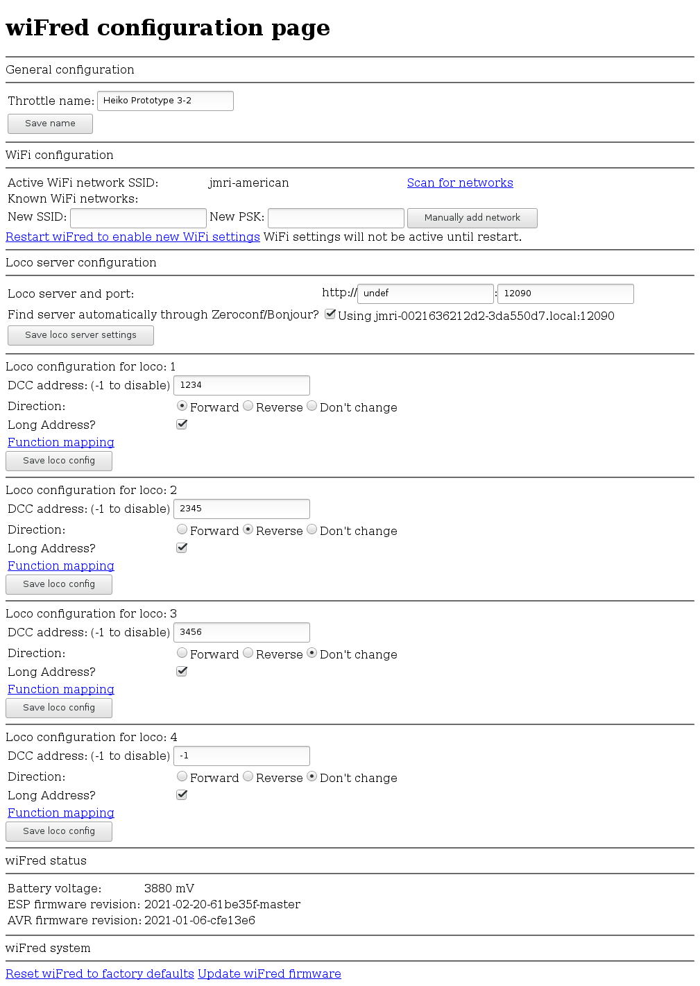
General configuration
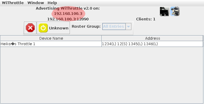
In the "General configuration" section there is only one configuration option: The throttle name. This is a free-form identification string of the throttle. It shows up in the wiThrottle window of JMRI as shown in Screenshot of wiThrottle screen showing one throttle connected and can be used to identify the throttle during configuration.
|
|
The wiFred also announces its presence on the WiFi network through Bonjour/Zeroconf using a sanitized version of the name, i.e. a throttle called "Heiko Prototype 2-2" will announce its presence as heikoprototype22.local when not in configuration mode. |
WiFi configuration
The "WiFi configuration" section shows a list of configured WiFi networks. The wiFred will connect to any network in this list, choosing the strongest one if multiple configured networks are in range.
Existing entries can be removed by clicking on the "Remove SSID" button in the line of the network that shall be removed.
New entries can be added either by manually entering the SSID and PSK[2] if required and clicking the "Manually add network" button or by clicking on the "Scan for networks" link which takes the user to the page shown in Screenshot of wiFred "Scan for WiFi"-page.
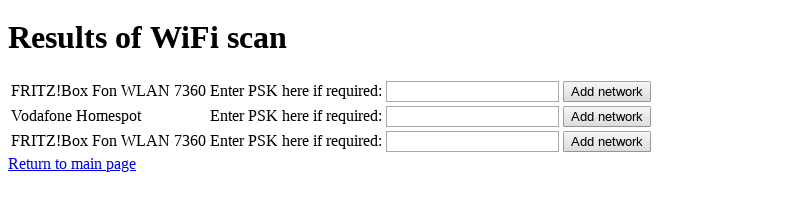
This page will take a few seconds to load, since the scan for networks has to be completed first. It shows all the networks found during the scan. Networks can be added to the list by clicking the "Add network" button, after entering the PSK[2] in the field next to it.
|
|
The wiFred does not support WPS and it won’t accept multiple networks with the same SSID but different PSKs. More details regarding the network requirements can be found in Options for server setup. |
The new WiFi configuration will not be activated until the wiFred is restarted, either through a power-cycle or by clicking on the "Restart wiFred to enable new WiFi-settings" link on the configuration page.
Loco server configuration
Following the WiFi configuration, the section "Loco server configuration" allows configuring the wiThrottle server to which the wiFred shall connect. The default setting - automatically detect server - works well if there is only one wiThrottle server on the network. It will connect to any server announcing its presence on port 12090 through Zeroconf/Bonjour, the result of the Zeroconf/Bonjour-search will be shown here when the wiFred has automatically discovered a server.
Loco configuration
Following the "Loco server configuration", there are four identical sections assigned to the four different locomotives which can be controlled with this throttle. Each section consists of the following settings:
- DCC address
-
Can be a short address between 1 and 127 (also used for consists) or a long address between 0 and 10239.
|
|
Short addresses between 1 and 127 are not the same as long addresses between 1 and 127, and many DCC systems do not support all those addresses.[3] A DCC address that the DCC system does not support is silently ignored. |
If this is set to -1, the corresponding loco is disabled.
- Long address?
-
Checkbox to change the behaviour of the DCC address input field described above.
- Direction
-
This has three options:
-
Forward: Loco will travel forwards if wiFred is set to forwards and vice versa
-
Reverse: Loco will travel backwards if wiFred is set to forwards and vice versa
-
Don’t change: Loco will continue to travel in the same direction it was set to when it was activated and switch direction when the wiFred switches direction
-
- Function mapping
-
Link to the function mapping subpage for the corresponding loco, as described in DCC function configuration. Clicking this link will lose all information entered on the current page and take the web browser to a different subpage.
|
|
Reminder: Changes are saved using the "Save loco config" button which may look different in different web browsers (firefox shown). |
DCC function configuration
By default, if a function key is pressed, the throttle will send the appropriate commands to every loco under control. Under certain circumstances, this may not be desired - the obvious example being a loco in the middle of a multi-unit consist, which should not have lights or ditchlights. So this page - shown in Screenshot of wiFred function handling config page - offers the option to chose between three different settings for every function on each of the four locomotives (one page per locomotive):
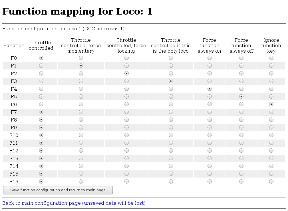
- Throttle controlled
-
When the first loco is enabled by moving the selection switch to the "selected" position, the current status of the function is queried and saved. When selecting the next loco, the function status is set to be the same. Afterwards, key presses are handed through to the loco. Whether the function will be momentary[4] or locking[5] will be determined by the server, in the case of JMRI by the roster entry.
- Throttle controlled, force momentary
-
Function key will be handed through to the loco as a momentary[4] function.
- Throttle controlled, force locking
-
As described for Throttle controlled but the function will be forced to be locking[5] regardless of the server settings[6].
- Throttle controlled if this is the only loco
-
As described for Throttle controlled, force locking but the function key will only be toggling the function if no other loco is enabled. This allows for i.e. turning headlights and rearlights on and off on individual locos before assembling a consist.
- Force function always on
-
The function will be forced on when the loco is activated and kept on regardless of key presses[7].
- Force function always off
-
The function will be forced off when the loco is activated and kept off regardless of key presses.
- Ignore function key
-
No function commands will be sent to this loco.
|
|
Reminder: Changes are saved using the "Save function configuration" button which may look different in different web browsers (firefox shown). |
wiFred status
The "wiFred status" section shows the current battery voltage, as measured by the wiFred. This is updated on reloading the page, not continuosly.
It also shows the current firmware version(s).
wiFred system
In the wiFred system section of the configuration page, various settings related to the hardware can be changed.
The first setting concerns wiFreds with an On-Off-On direction switch and determines what the center position will do. The options are:
- Ignore
-
Don’t do anything special when the switch is in the center position - just continue as before, same direction, speed controlled by speed potentiometer. Reversing entirely will trigger an emergency stop.
- Zero speed
-
Keep the direction but send out zero speed to all locos. This setting is intended for locos with high momentum settings. Reversing quicker than within half a second will trigger an emergency stop, otherwise the locos will resume their old speed setting in the opposite direction.[8]
- Set F<n>
-
Simulates a function key press when switching from forward to center position and a key release when switching from center position to reverse (and vice versa).[9] This is intended for locos with either a brake function or ESU’s Drive Hold on a function key. The speed commands sent to the loco will still be controlled by the speed potentiometer while the direction switch is in the center position. Reversing quicker than within half a second will trigger an emergency stop, otherwise the throttle will continue to send speed commands according to the speed potentiometer position.
The section concludes with two links:
-
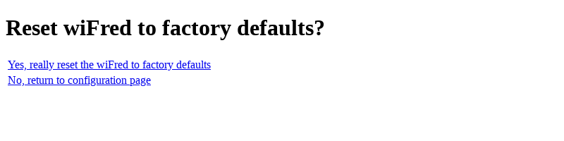
Reset wiFred to factory defaults - which leads to a confirmation page shown in Screenshot of wiFred configuration reset page to reset all configuration data to factory defaults as on a new wiFred.
-
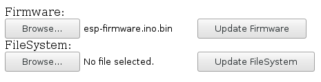
Update wiFred firmware - which leads to a firmware update page shown in Screenshot of wiFred firmware update page to update the wiFred firmware of the ESP8266 / ESP32-S2. Find the .bin-file from the arduino build folder or from the [Github repository for wiFred], click on "Browse", navigate to the .bin-file and finally initiate the update with a click on "Update Firmware" - which will take a while.
|
|
It may be necessary to power down the wiFred entirely for a firmware update to restart properly. |
|
|
On a wiFred version from 0.6 onwards with an ESP32-S2 MCU, resetting to factory defaults can also be done by holding down the ESTOP key for five seconds at startup. |
Options for server setup
Components required to get the wiFred running
Overview of devices required to run trains with the wiFred shows the connections between the devices required to run trains using the wiFred.
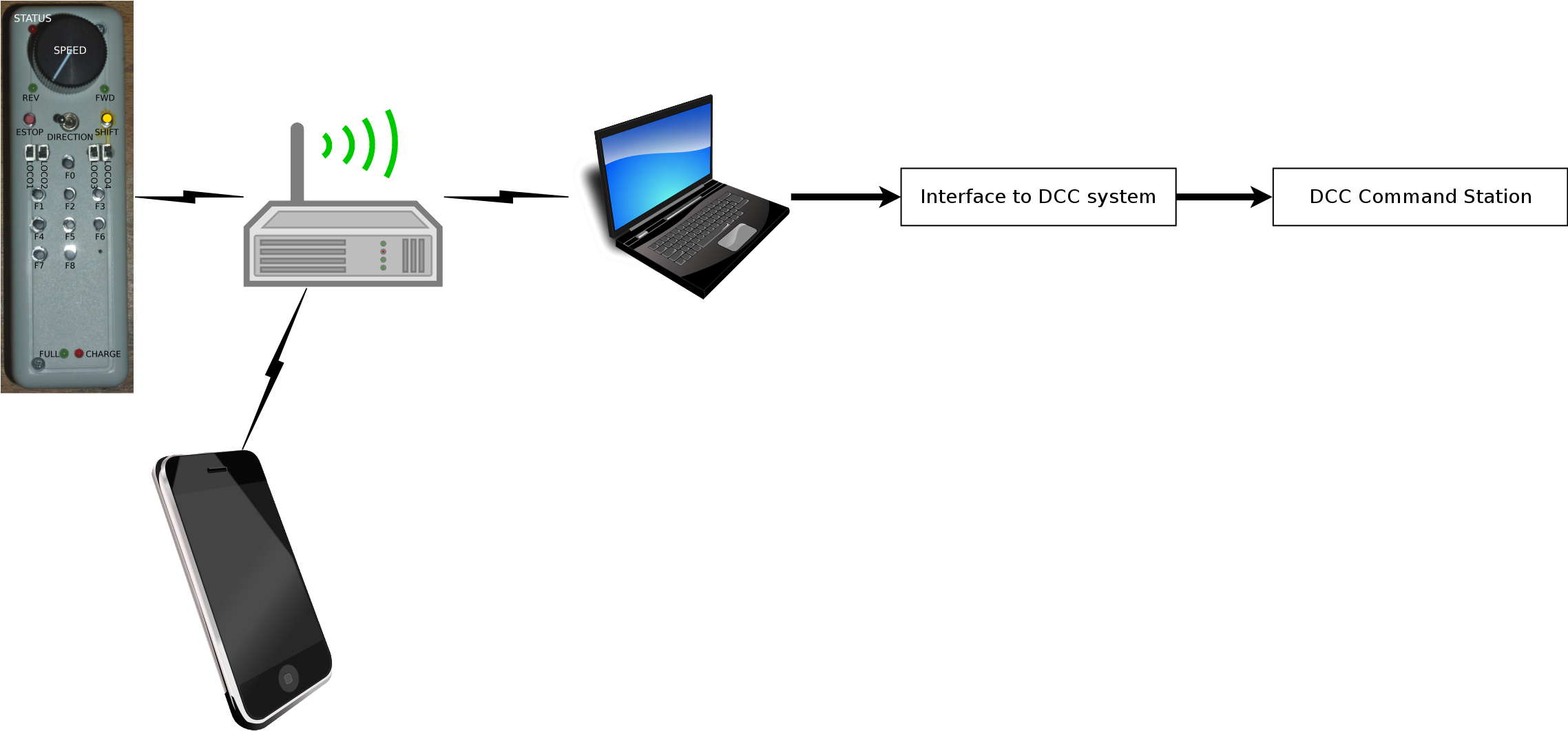
The symbols in Overview of devices required to run trains with the wiFred symbolize the following parts:
-
An IEEE 802.11b/g/n 2.4 GHz WiFi access point described in detail in WiFi access point requirements
-
A PC or laptop computer with Windows, Linux or MacOS to run the JMRI server described in detail in JMRI server requirements
-
A way to connect the JMRI server to the model railroading layout described in detail in Layout connection options
-
A device with a web browser connected to the same network as the wiFred to configure it - can be the same physical device as the one running the server, if it meets the requirements in Computer or smartphone to configure wiFred
Multiple options for every step or combining these steps are described in the following sections.
|
|
Basically, if a layout is set up to run trains with a smartphone running wiThrottle or EngineDriver, a wiFred should work with no changes to the layout configuration. If a layout is set up in a way that trains can be run from a JMRI screen throttle on a computer, only a WiFi connection to the JMRI computer needs to be added. |
Out-of-the-box server-side options
A pretty much out-of-the-box solution for a Raspberry Pi is provided by [Steve Todd], which creates its own WiFi network, auto-detects multiple options to interface to a DCC layout and starts a wiThrottle server. It has been tested in the JMRI 4.16 and JMRI 4.20 versions to work with the wiFred, connecting to a Z21 black through both an RRCircuits LocoBuffer USB and a Digitrax PR3 via Loconet.
Although untested so far, adding a [Digitrax LNWI] to a Digitrax system or an [MRC Prodigy WiFi] to an MRC system should allow the wiFred to run locos out-of-the-box as well.
Step by step instructions for a Windows computer
This has been tested on a Windows 7 64Bit laptop computer with a 2.4GHz WiFi card inside the PC.
Installation
-
Install HostedNetworkStarter
-
Install DHCP server - download and extract all the files from the zip file to somewhere on your harddrive, for example C:\DHCPServer
-
Install a JDK, version 8 and 11 have been tested. For example, Version OpenJDK 11 (LTS), JVM HotSpot. Choose the 64bit version for most modern hardware, 32bit only if you are running a 32bit operating system. Easiest option: MSI file, download and install.
-
Install JMRI - versions tested to run with the wiFred include 4.14, 4.16, 4.18 and 4.20. Most recent production version recommended.
|
|
Windows 10 provides a Hotspot feature that will work in place of HostedNetworkStarter and DHCP server, so you can jump right into installing JDK and JMRI. |
Configuration
-
Start HostedNetworkStarter from the start menu, enter a Network Name and Network Key, then hit the Start button. Note the "Hosted Network Connection Name" for the next step
-
Start the DHCP server wizard from C:\DHCPServer\dhcpwiz.exe, select the network with the name that’s the same as the "Hosted Network Connection Name" from the step before, hit "Next" a few times (deselecting all additional supported protocols), Write INI file, Start Service and Configure Firewall Exceptions
-
Start JMRI using the DecoderPro icon on the desktop, setup your layout connection, test if you can run a loco with a JMRI throttle
-
Within JMRI, start the WiThrottle Server from the Actions menu. If a firewall popup comes up, allow all.
-
Within JMRI, edit the Preferences from the Edit menu, choose WiThrottle on the left pane, click the "Start automatically with application" checkbox. All the Allowed Controls can be disabled.
Running
-
Start HostedNetworkStarter from the start menu, enter a Network Name and Network Key, then hit the Start button.
-
Start JMRI using the DecoderPro icon on the desktop
WiFi access point requirements
The wiFred will work on basically any 2.4GHz IEEE802.11b or -g WiFi network that will accept new devices and provide them with an IPv4 address through a DHCP server. It supports open networks or WPA2 encryption, though not WPS.
It has successfully been tested with a FRITZ!Box, a random cable router, multiple public WiFi networks and several software hotspots including Linux hostapd both on a first generation Intel Atom netbook and a Raspberry Pi, the Windows 10 Hotspot and a Windows 7 software as described in Step by step instructions for a Windows computer.
|
|
Some WiFi access points and routers offer a feature called "Wireless Isolation" or similar that will forbid connected devices from connecting to each other. This feature should be disabled for wiFreds to find their server and to be configured. |
JMRI server requirements
Any PC that can run at least Java 8 will be able to run the JMRI server. Even old 32Bit first generation netbook computers like the 2008 Eee-PC have more than enough computing power for that task. There are JMRI versions for Windows, Linux or MacOS available, so any of these operating systems should be fine.
Layout connection options
[JMRI] supports a multitude of different connections to the layout as described in [Supported Hardware]. In general, if a JMRI installation can run a loco on the layout, it’s a simple matter of connecting the JMRI computer to a WiFi access point (if not already connected) and starting the wiThrottle server from the Actions-menu inside DecoderPro.
The wiFred has been tested to work with a LocoBufferUSB or a Digitrax PR3 connected via Loconet to an Intellibox, a Z21 black, a DCS 51 Zephyr xtra or a Minibox 2 DIY DCC central station. It has also been used to run a loco on a SPROG programmer.
Computer or smartphone to configure wiFred
Webbrowser, Zeroconf. Avahi. Bonjour (iTunes?). MacOS out of the box? iOS? Android?
For initial configuration of the wiFred, most of the devices mentioned above can be omitted. As shown in For initial configuration, the requirements are very small, only a WiFi capable device with a web browser is required.
Tested with iOS 13 and iOS 14, Android 9 and 10 as well as Firefox on Linux, the initial configuration page is automatically loaded when the device is connected to the wiFred-configXXXX-network.
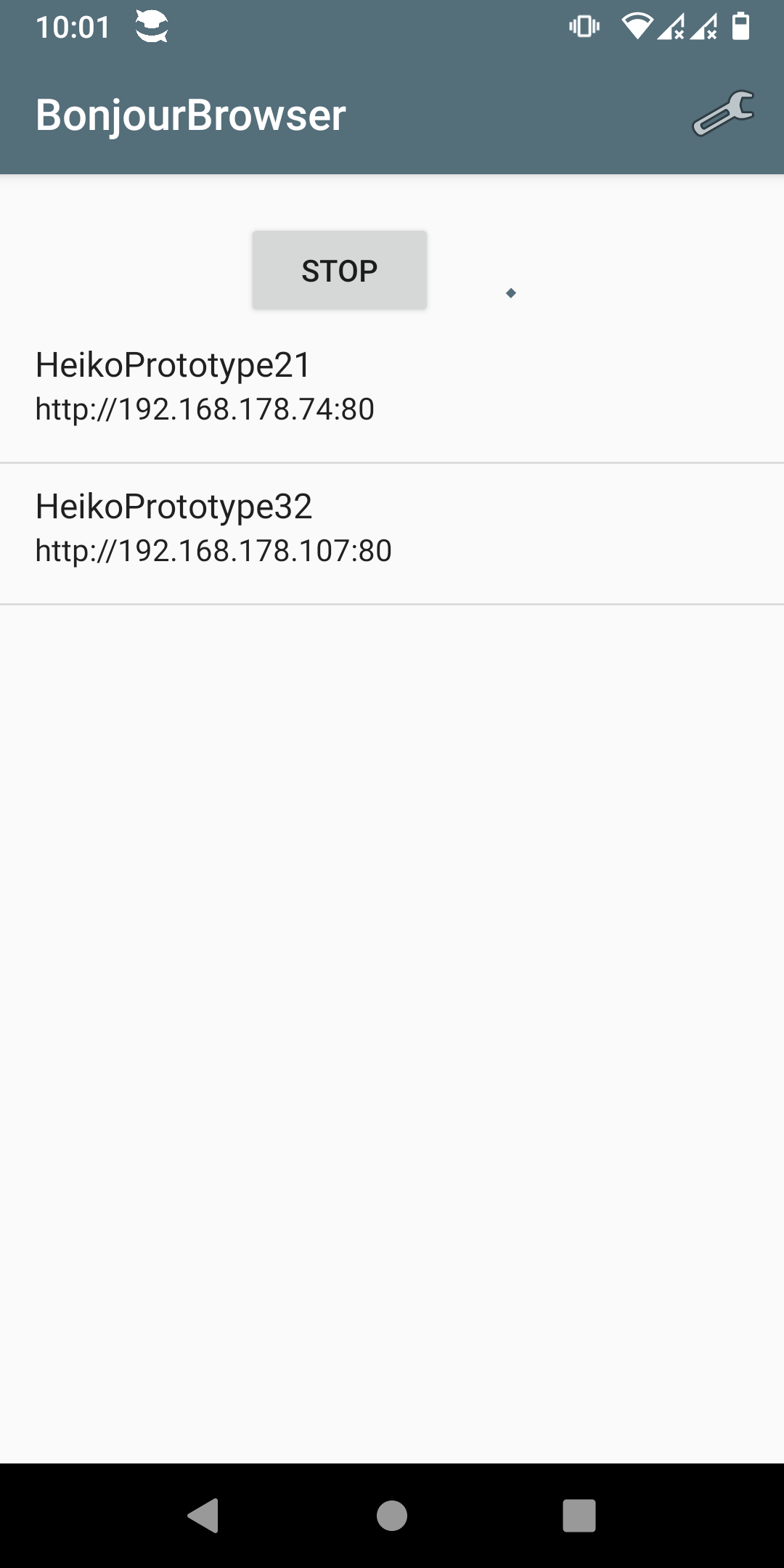
For regular configuration, once the wiFred has successfully connected to a WiFi network and put into configuration mode, Bonjour/Zeroconf/mDNS support is required to find the device announcing itself as http://config.local. This service is provided on Linux by a software package called avahi, should work out of the box on iOS and MacOS and can be installed on Windows with iTunes. For mobile operating systems, there are apps called Discovery for iOS and BonjourBrowser for Android which not only translate http://config.local to point to the configuration website of the one wiFred on the network that is in configuration mode but also browse all wiFreds currently announcing their presence. User interface of BonjourBrowser, showing two wiFreds active on the network. shows a screenshot of the Android version. Clicking on a device will open a browser to its configuration website.
|
|
The wiFred is designed to be configured in configuration mode. If the IP address or the name of the throttle during normal operation is known, the configuration pages can also be accessed by pointing a web browser to it at any time while it is connected. This is mostly untested and therefore not recommended while the throttle is running locos, as it may lead to a temporarily inconsistent configuration. At the very least, deactivating and re-activating a loco with the respective loco selection switch will be required for changed settings to take effect. |
Support for configuration software
To support a specialized configuration software, the wiFred will send a UDP broadcast upon successfully connecting to a WiFi network and present its configuration at /api/getConfigXML.
For more information, contact Detlef Born.
Hardware description
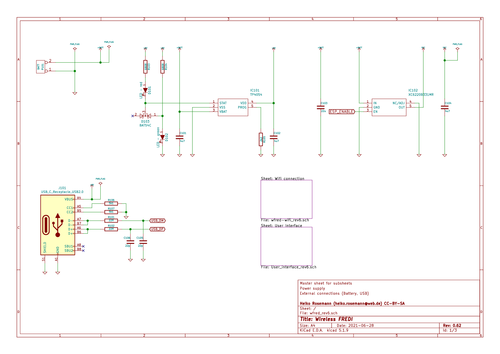
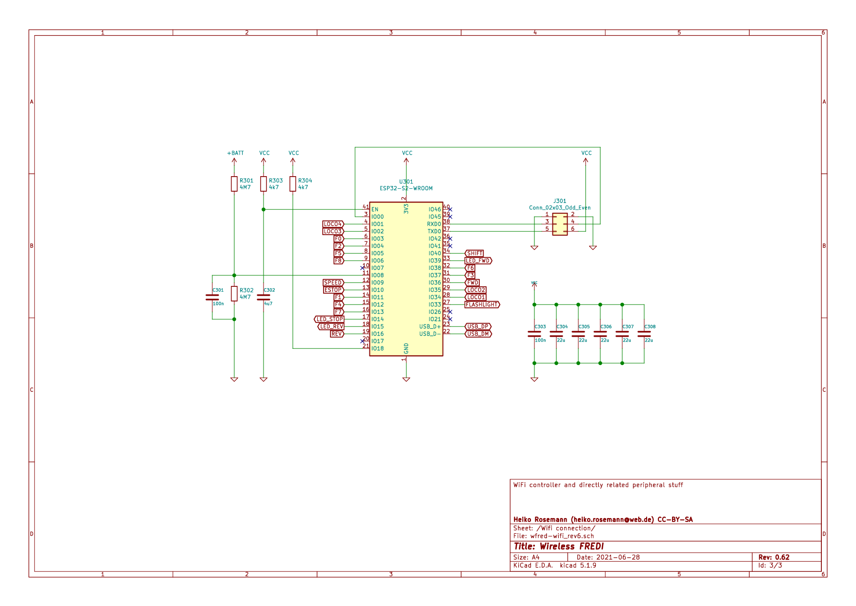
From revision 0.6 onwards
The wiFred hardware is centered around an ESP32-S2-WROOM module that controls the LEDs and reads the switches, push buttons and speed potentiometer. It gets its power from a single cell LiPo battery through a 3.3V low drop linear voltage regulator that is activated directly from the loco selection switches combined through a set of diodes. An RC lowpass will delay turning off the wiFred by a couple of seconds.
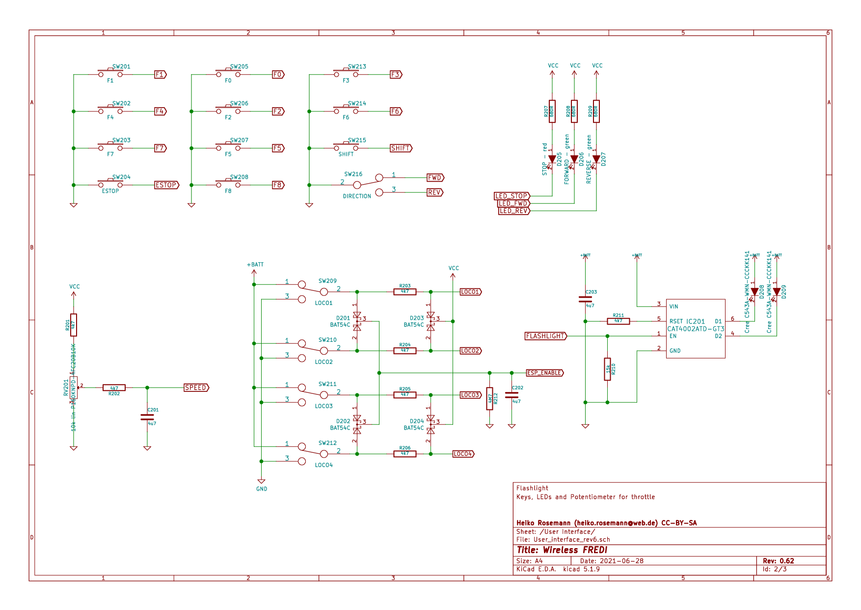
Optionally, two white 5 mm-LEDs protruding from the top of the PCB can be installed to serve as a flashlight. They are driven by a constant-current source directly from the battery and enabled when pushing the yellow SHIFT key.
The ESP32-S2 also monitors the battery voltage, going into sleep mode when the battery voltage drops too low. This should drop power consumption to a reasonably safe value, even though not as low as it can go when all the loco selection switches are off. Charging the battery can be done through the integrated USB port with two LEDs showing the charging status.
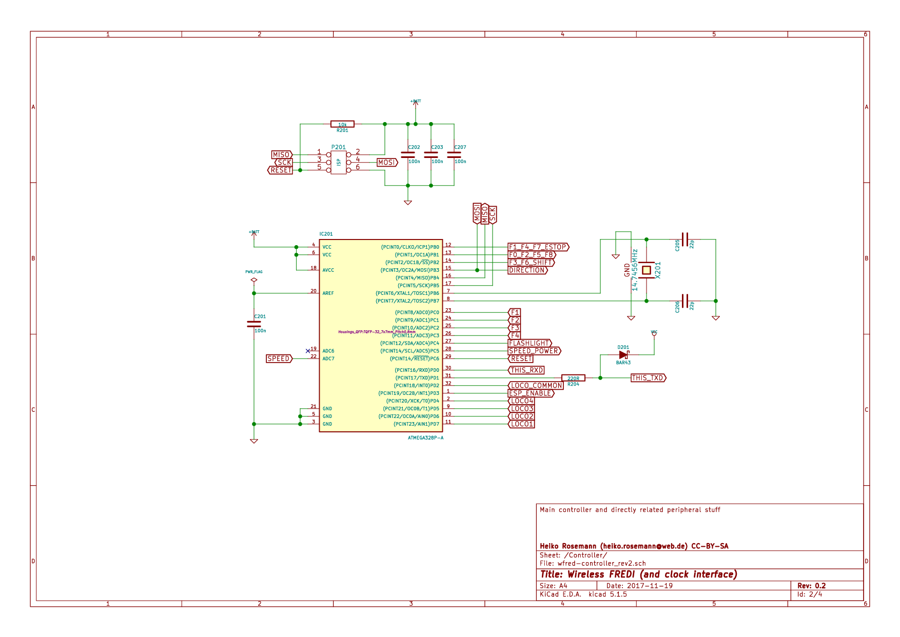
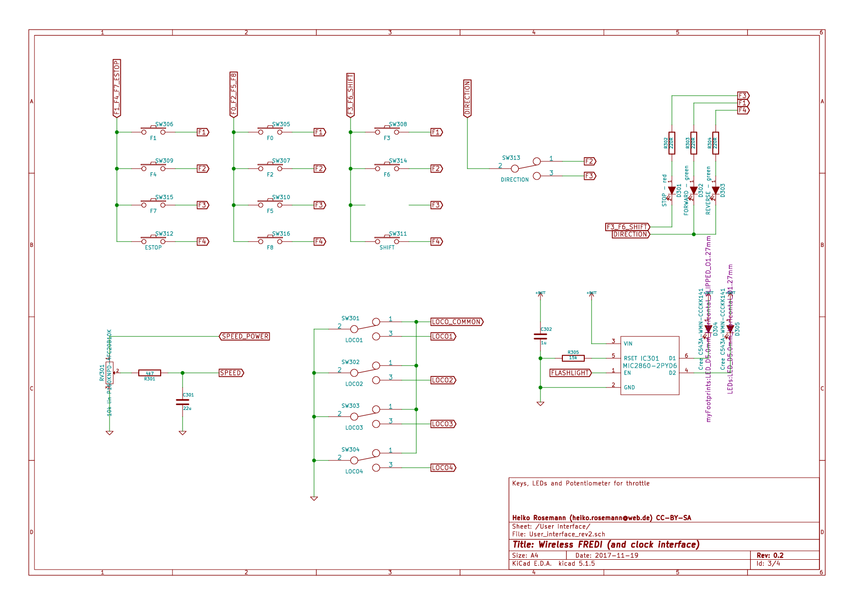
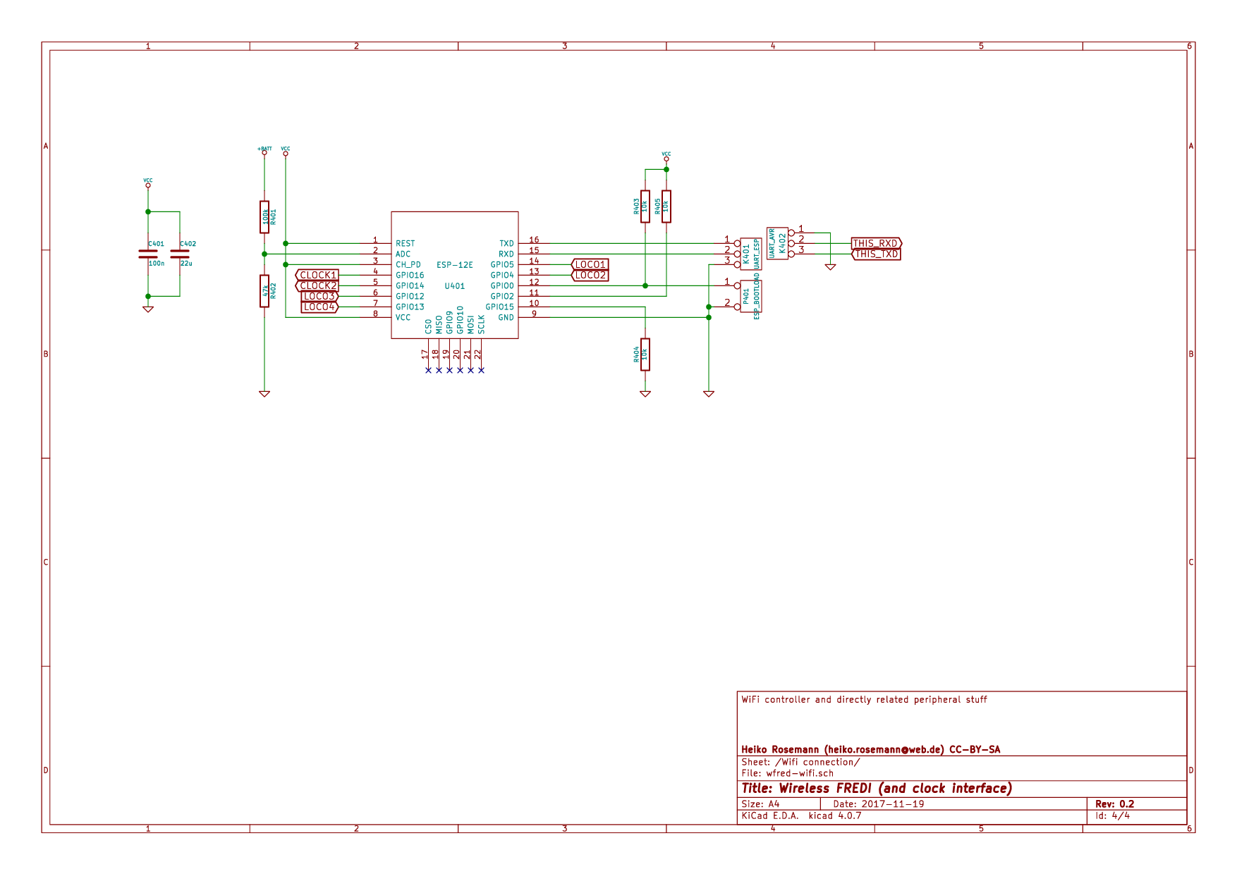
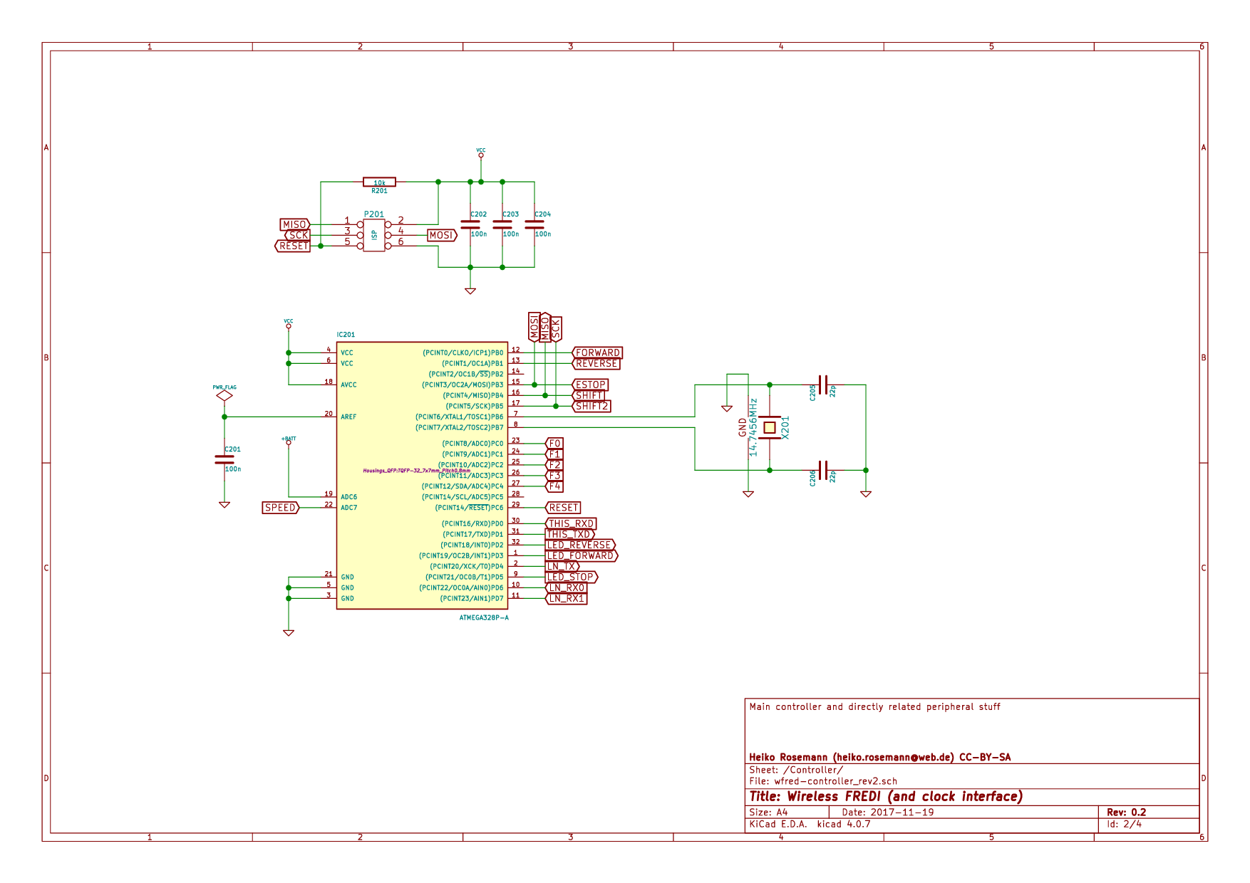
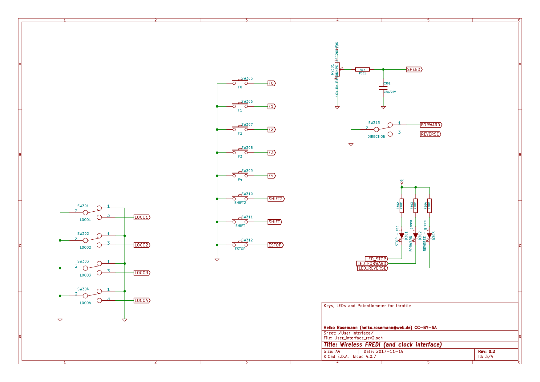
The schematic is split into several pages and can be found in Master schematic sheet with battery connector, charging circuit and power supply to Schematic sheet for user interface (Keys, switches, LEDs, poti and flashlight). It has been created with kicad and is available on the [Github repository for wiFred] along with the PCB design.
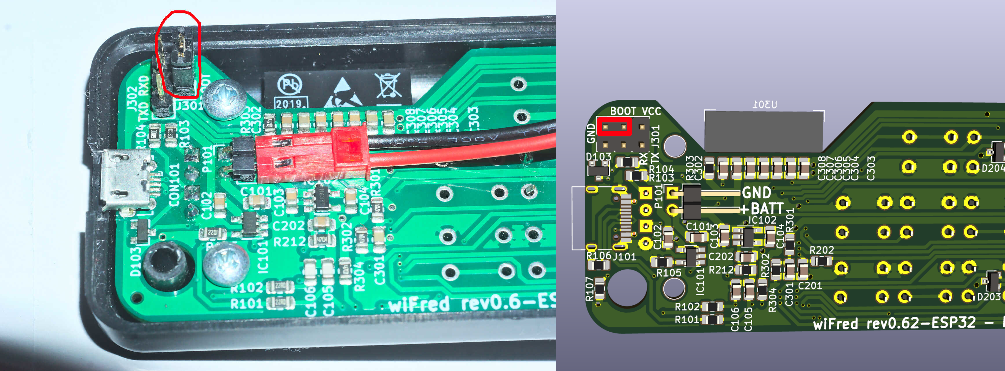
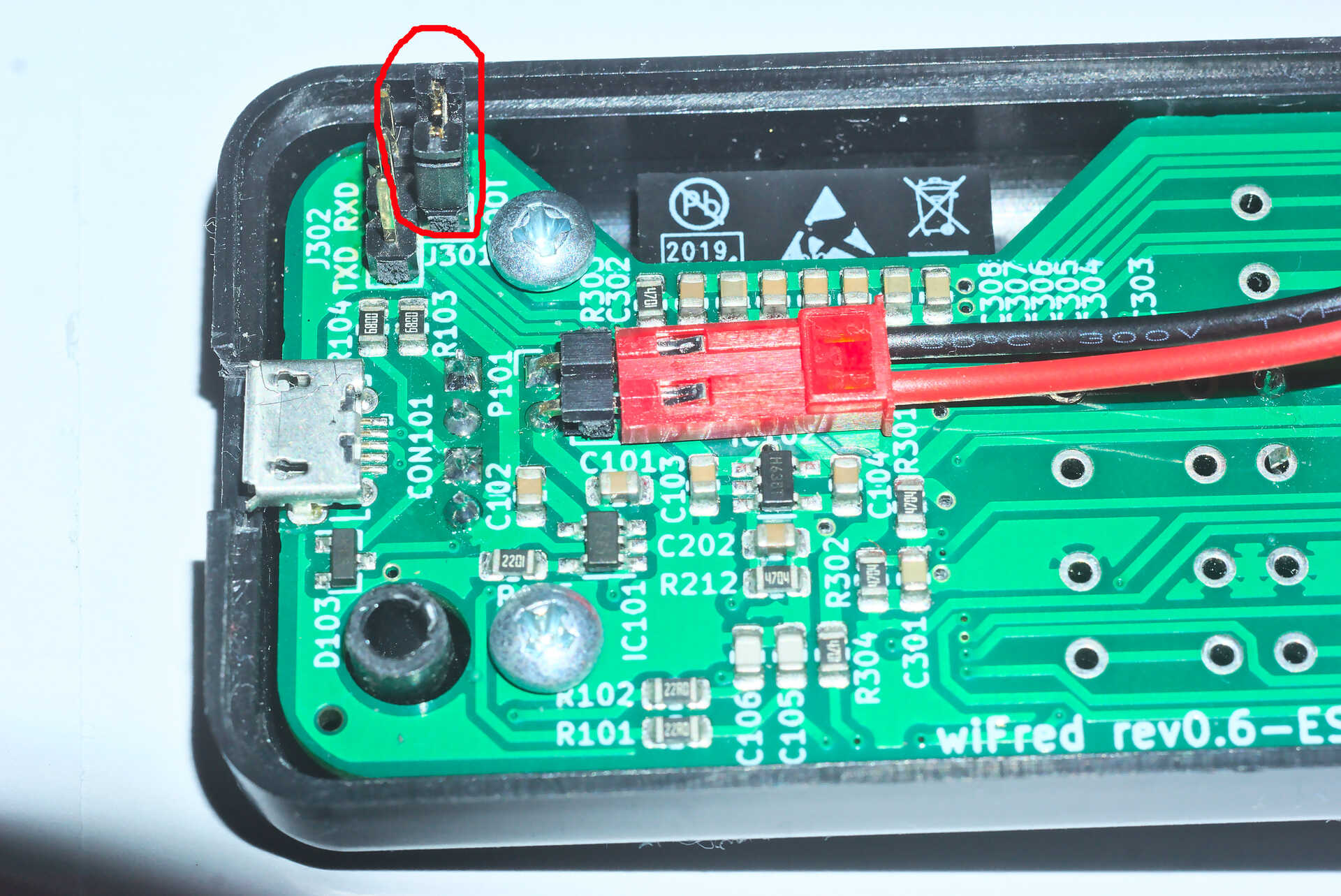
Writing the firmware to the ESP32-S2-WROOM
To place the ESP32-S2 into firmware flashing mode, a jumper has to be installed on the BOOT pins as shown in Display of boot jumper - left from 0.6 prototype, right from 0.62 rendering when the device is powered up. After entering boot mode, the ESP32-S2 will register as a USB CDC device when connected to a PC and can be programmed through it. Alternately, the serial port at the TXD/RXD pins can be used. The serial port needs to be at 3.3 V-levels like from an FTDI232-device run at 3.3 V.
All files in the software/esp-firmware-subdirectory of the [Github repository for wiFred] need to be placed in a folder, then the main sketch esp-firmware.ino needs to be opened with the Arduino IDE. Settings for the Arduino IDE can be found inside the main file, programming the device should work using the Upload-button in the Sketch-menu. An alternate solution using a pre-compiled firmware and esptool.py may be documented in the future.
Hints for building revision 0.6
All the SMD parts and connectors in List of bottom side components - SMDs and pin headers - for the wiFred PCB from revision 0.6 are located on the bottom side, so they can easily be installed by an automated PCB assembly service. Gerber files and location files will be made available on the [Github repository for wiFred]. They are no smaller than 0805, though, so it should be possible for experienced electronics hobbyists to hand-solder them as well, although the USB-C-connector has a very small pitch.
| Designator | Package | Designation |
|---|---|---|
C106, C105 |
C_0805_2012Metric_Pad1.15x1.40mm_HandSolder |
22p |
C201, C302, C102, C203, C202, C104, C101 |
C_0805_2012Metric_Pad1.15x1.40mm_HandSolder |
4u7 |
C303, C301 |
C_0805_2012Metric_Pad1.15x1.40mm_HandSolder |
100n |
C308, C307, C306, C305, C103, C304 |
C_0805_2012Metric_Pad1.15x1.40mm_HandSolder |
22u |
D103, D204, D203, D202, D201 |
SOT-23 |
BAT54C |
IC101 |
SOT-23-5_HandSoldering |
TP4054 |
IC102 |
SOT-23-5_HandSoldering |
XC6220B331MR |
IC201 |
SOT-23-6_Handsoldering |
CAT4002ATD-GT3 |
J101 |
USB_C_Receptacle_HRO_TYPE-C-31-M-12 |
USB_C_Receptacle_USB2.0 |
J301 |
PinHeader_2x03_P2.54mm_Vertical |
Conn_02x03_Odd_Even |
P101 |
PinHeader_1x02_P2.54mm_Horizontal |
BATT |
R102, R101 |
R_0805_2012Metric_Pad1.15x1.40mm_HandSolder |
22R |
R103, R209, R208, R207, R104 |
R_0805_2012Metric_Pad1.15x1.40mm_HandSolder |
680R |
R105 |
R_0805_2012Metric_Pad1.15x1.40mm_HandSolder |
2k2 |
R107, R106 |
R_0805_2012Metric_Pad1.15x1.40mm_HandSolder |
5k1 |
R212, R302, R301 |
R_0805_2012Metric_Pad1.15x1.40mm_HandSolder |
4M7 |
R303, R304, R206, R211, R205, R204, R203, R202, R201 |
R_0805_2012Metric_Pad1.15x1.40mm_HandSolder |
4k7 |
Then - as shown in List of top side components - ESP32-S2-WROOM and user interface - for the wiFred PCB from revision 0.6 - there is only the ESP32-S2-WROOM module on the top of the PCB and all the switches, push buttons, potentiometer and LEDs. After installing the ESP32-S2-WROOM, the direction switch should be screwed into the PCB with an 8 mm hex nut first, then attached to it’s pads using the cutoffs from the LEDs, and the speed potentiometer should be screwed into the PCB with a 10 mm hex nut before soldering its leads.
For all other switches, push buttons and LEDs, it is recommended to drill the holes in the housing first, then place the parts on the PCB and screw the PCB into the housing before soldering the parts. Holes for the pushbutton switches should be drilled at 3.5 mm diameter. Holes for the LEDs should be drilled at 3 mm diameter and holes for the speed potentiometer at 8 mm, for the direction switch at 6.5 mm diameter. The cutouts for the loco selection switches are best drilled at 1.5 mm and extended to fit with a jigsaw or a sharp hobby knife and a file. The easiest approach is a laser engraved housing - PDF and DXF files of the markings are available on the [Github repository for wiFred] as well.
| Designator | Package | Designation |
|---|---|---|
D101 |
LED_D3.0mm |
LED - red |
D102 |
LED_D3.0mm |
LED - green |
D205 |
LED_D3.0mm |
STOP - red |
D206 |
LED_D3.0mm |
FORWARD - green |
D207 |
LED_D3.0mm |
REVERSE - green |
D208 |
LED_D5.0mm_Horicontal_FLIPPED_O1.27mm |
Cree C543A-WMN-CCCKK141 |
D209 |
LED_D5.0mm_Horizontal_O1.27mm_Z3.0mm_Clear |
Cree C543A-WMN-CCCKK141 |
RV201 |
P160KNPD |
10k lin P160KNPD-4FC20B10K |
SW201 |
SW_PUSH_6mm_H9.5mm |
F1 |
SW202 |
SW_PUSH_6mm_H9.5mm |
F4 |
SW203 |
SW_PUSH_6mm_H9.5mm |
F7 |
SW204 |
SW_PUSH_6mm_H9.5mm |
ESTOP |
SW205 |
SW_PUSH_6mm_H9.5mm |
F0 |
SW206 |
SW_PUSH_6mm_H9.5mm |
F2 |
SW207 |
SW_PUSH_6mm_H9.5mm |
F5 |
SW208 |
SW_PUSH_6mm_H9.5mm |
F8 |
SW209 |
OS102011MS2Q |
LOCO1 |
SW210 |
OS102011MS2Q |
LOCO2 |
SW211 |
OS102011MS2Q |
LOCO3 |
SW212 |
OS102011MS2Q |
LOCO4 |
SW213 |
SW_PUSH_6mm_H9.5mm |
F3 |
SW214 |
SW_PUSH_6mm_H9.5mm |
F6 |
SW215 |
SW_PUSH_6mm_H9.5mm |
SHIFT |
SW216 |
100SP1T1B1M1QEH |
DIRECTION |
U301 |
ESP32-S2-WROVER-HandSoldering |
ESP32-S2-WROOM |
To form a complete BOM, also include the parts listed in List of components for the wiFred from revision 0.6 excluding electronic parts to solder to PCB which are not soldered to the PCB but used in assembly later on.
| Designator | Package | Designation |
|---|---|---|
B1 |
Battery |
Lithium battery 1700mAh |
H1a |
Housing black |
Strapubox 2090 |
or H1b |
Housing white |
Strapubox 2090 |
J1 |
Jumper |
|
K1a |
Potentiometer Knob silver |
24mm |
or K1b |
Potentiometer Knob black |
24mm |
P1 |
PCB |
124mm x 35mm x 1.6mm |
S1, S2, S3, S4 |
Mounting Screws |
2,9mm x 6,5mm |
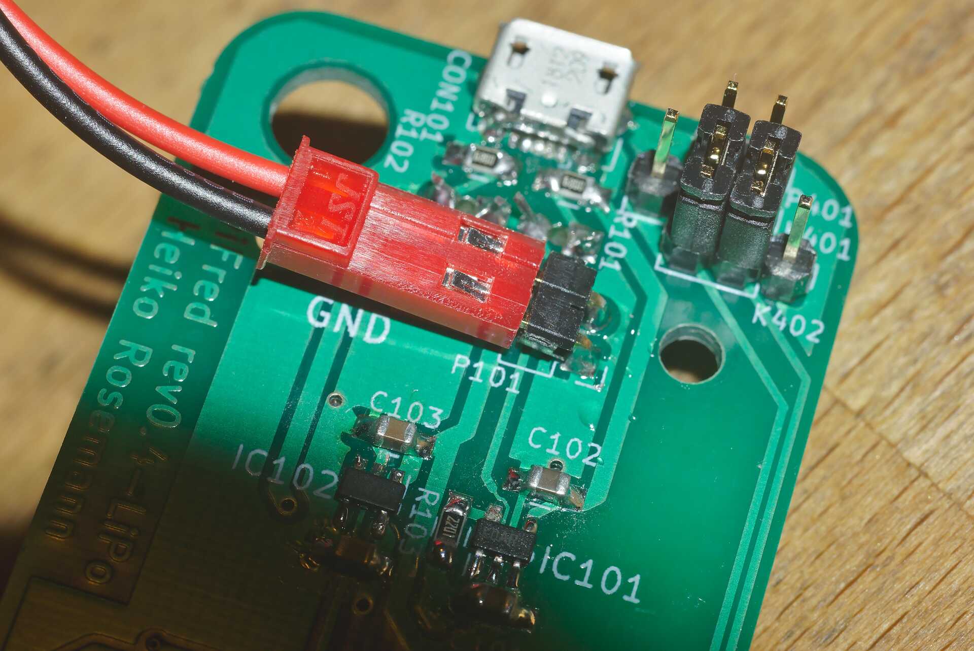
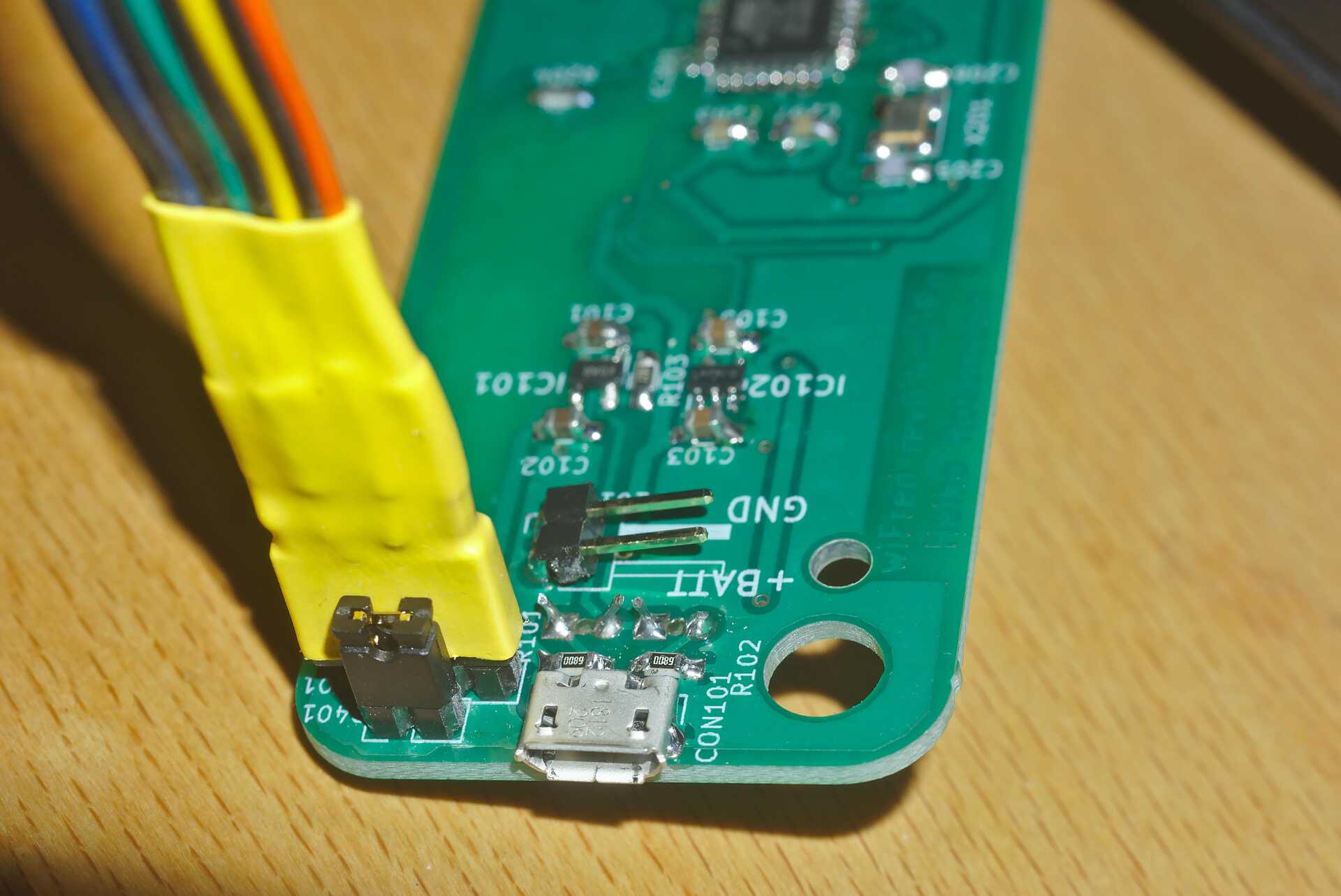
After assembling the PCB with all the components, the holes and cutouts in the enclosure most likely will have to be reworked / extended to actually fit the PCB, then the PCB can be screwed into the enclosure with four screws. Afterwards the battery should be connected to the BATT connector making sure the orientation is correct as shown in Connection of battery to P101 on revision 0.6 and up - black wire is GND, red wire is positve and printed on the PCB, then the battery should be glued to the bottom of the enclosure with double-sided tape so it does not collide with any parts on the PCB, particularly the pin headers and the direction switch.
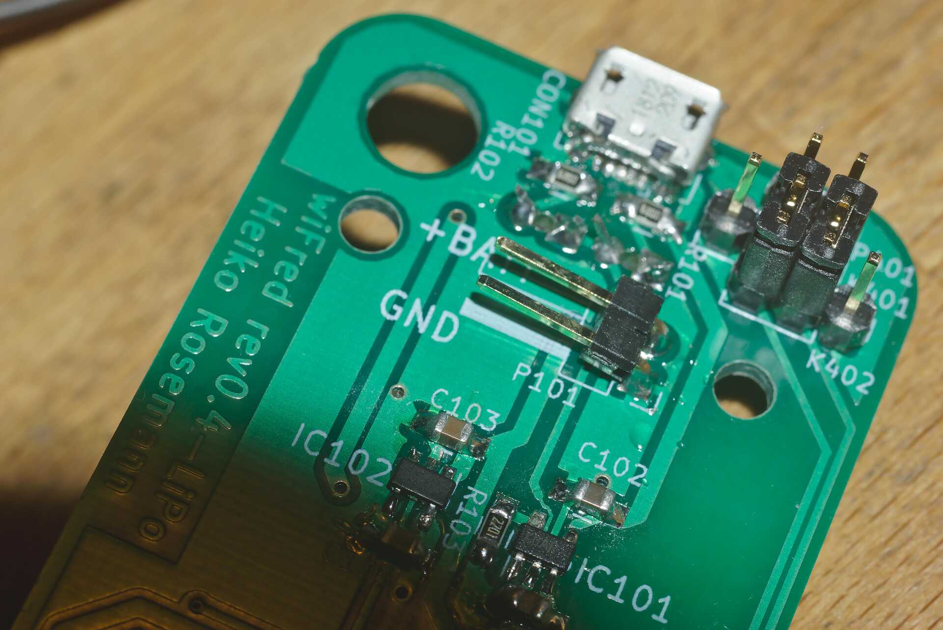
Up to revision 0.5
The wiFred hardware is centered around an ESP8266 for the WiFi connection. The ESP8266 communicates through its serial port with an ATMega 328P microcontroller which manages the power, controls the LEDs, reads the loco selection switches, speed potentiometer, direction switch and pushbutton switches for functions and emergency stop. The communication goes through a 2x3 pin header which enables the user to connect a programming cable to the same serial port if removing the jumpers.
Optionally, two white 5 mm-LEDs protruding from the top of the PCB can be installed to serve as a flashlight. They are driven by a constant-current source directly from the battery and enabled when pushing the yellow SHIFT key.
The wiFred is powered by a single cell LiPo battery. The ATMega 328P is connected directly to the LiPo cell, going into sleep mode when no loco selection switch is active, thereby reducing the power consumption to less than 1 µA. The ESP8266 is powered by a low-drop linear voltage regulator with an output voltage of 3 V which is disabled by the ATMega 328P when the device goes into standby.
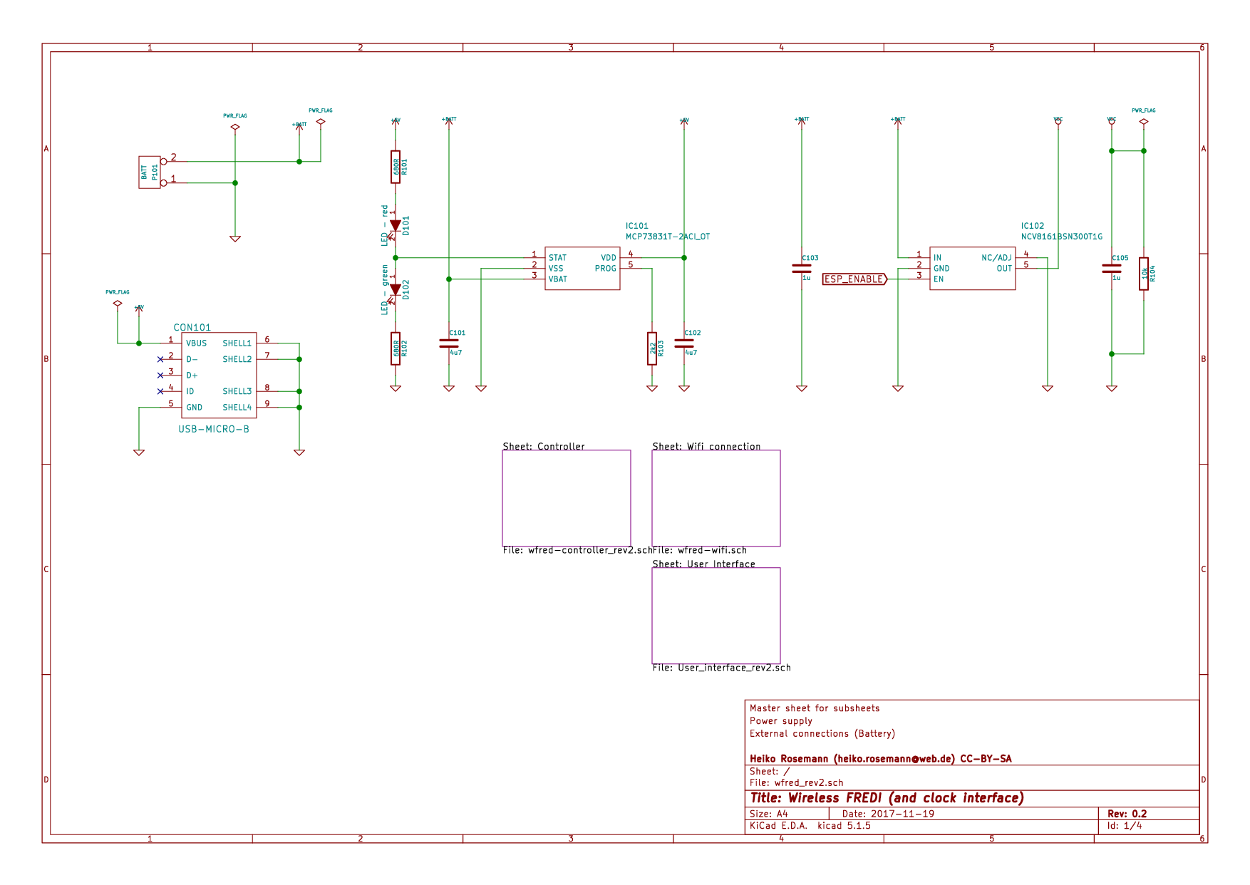
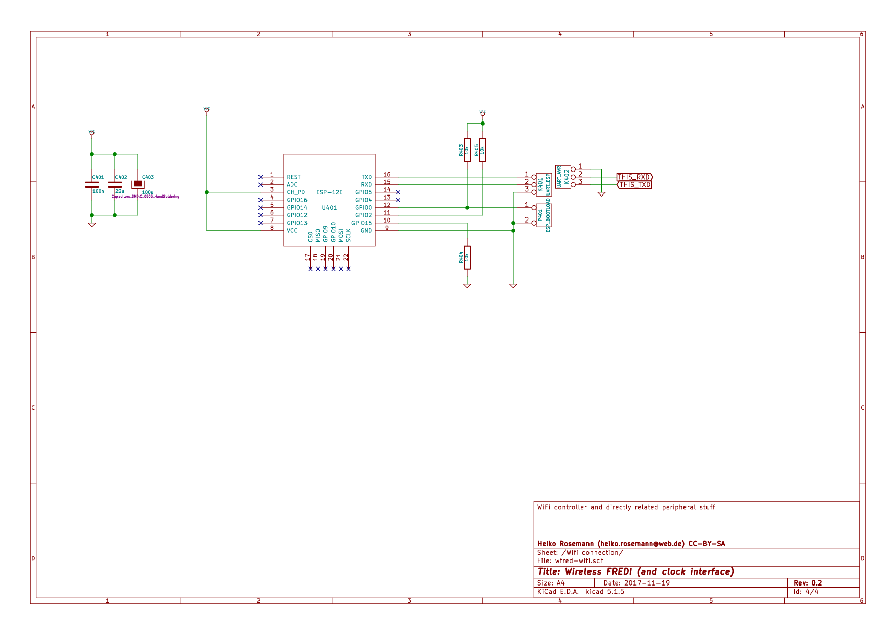
The schematic is split into several pages and can be found in Master schematic sheet with battery connector, charging circuit and power supply to Schematic sheet including pushbutton switches, loco selection switches, direction switch, speed potentiometer and flashlight LEDs with controller. It has been created with kicad and is available on the [Github repository for wiFred] along with the PCB design.
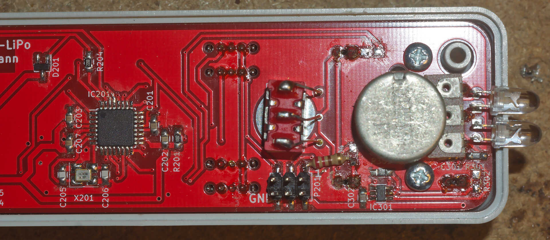
Required PCB fixes for wiFred revisions 0.5 and 0.51
Intensive use of the wiFred of revisions 0.5 and 0.51 revealed a mistake in the way the LEDs and key switches are connected to the AVR on PCBs with rev0.5 and rev0.51: In certain situations, pressing one function key will be read as multiple key presses. This is most obvious with F2, F5 or F8 also activating ESTOP. This document describes a fix which has been implemented successfully in many wiFreds and also incorporated into the rev0.52 PCB and schematic. It removes the LEDs from the key read-in matrix.
Tools and parts needed
This work requires some solder wick, a total of three 220-Ohm THT resistors of size 0207 (the usual 0.25W carbon film or 0.6W metal film types are fine) and some length of heat-shrink tube of about 2.4mm diameter.
To update the firmware, an AVR programmer for the regular AVR ISP connector P201 on the PCB is required.
How to fix, step by step
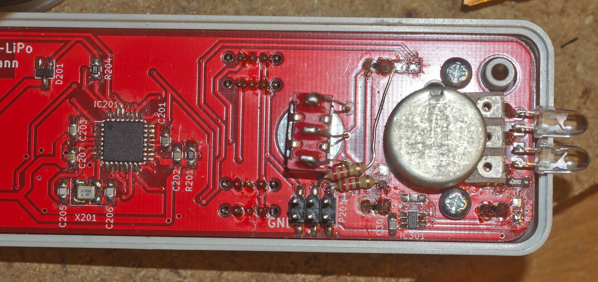
First, remove the SMD resistors R302, R303 and R304 as shown in PCB rev0.51 showing the half with resistors R302, R303 and R304 to be removed and PCB rev0.51 after removal of R302, R303 and R304 and clean their pads with some solder wick.
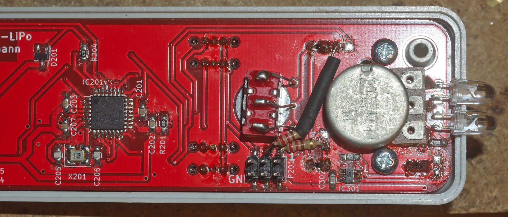
Next, get the first of the 220-Ohm THT resistors (size 0207), cut and bend the leads very short so it connects Pin 1 of P201 to the outer pad of former R304 and solder it as shown in PCB rev0.51 with the first of three replacement resistors installed.
The second 220-Ohm THT resistors needs a little more shaping of its leads. It should connect pin 3 of P201 (center pin in the upper row) with the inner, left pad of former R303, as shown in PCB rev0.51 with the second of three replacement resistors test-fit, but not yet soldered. As the longer lead of that resistor passes close to a couple of metal pieces in the wiFred, it is recommended to cut a piece of heat-shrink tube and fit it over the bare metal of the lead, as shown in PCB rev0.51 with the second of three replacement resistors soldered after covering the bare lead with heat-shrink tube. It is not required to actually shrink it as it will be held in place by the resistor and the solder point.
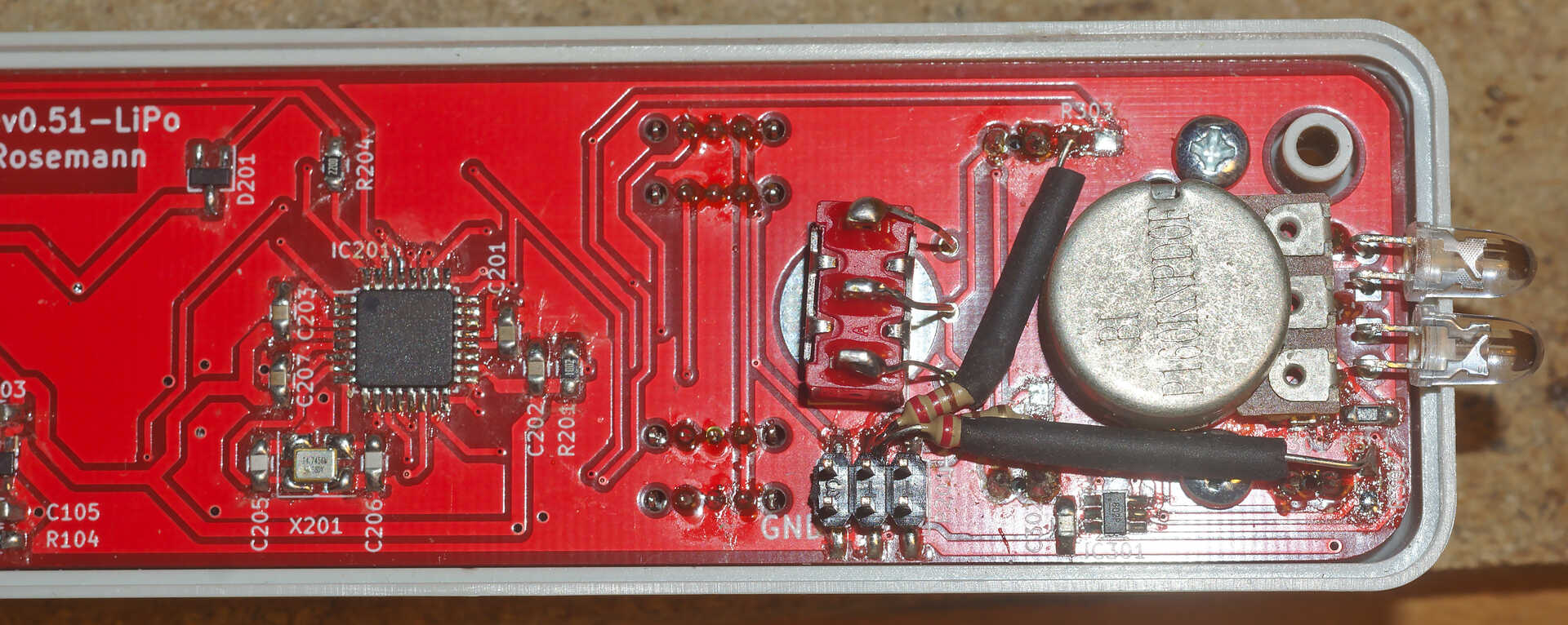
The final 220-Ohm THT resistor is installed in a similar fashion to the second one, also attaching to pin 3 of P201 and connecting it to the center (upper) pad of former R302 as shown in PCB rev0.51 with all three replacement resistors installed. It also has a long bare lead floating close to other metal parts, so insulation with heat-shrink tube is recommended. Also it blocks access to the lower right (in the picture) screw attaching the PCB to the housing, so either bend it a little different from the picture, remove the screw or make sure access to the top side of the PCB is not required.
Software required
To make the LEDs light up with their new connections, a new AVR firmware is required. It is distributed through the github repository and dated 2025-03-26.
Before updating the AVR firmware, it is recommended to update the ESP12 firmware through the web interface of the wiFred. As of this writing, any firmware with -esp12.bin in the filename should work, starting from 2022-10-16-ff2c954-esp12.bin.
Hints for building revisions up to 0.5
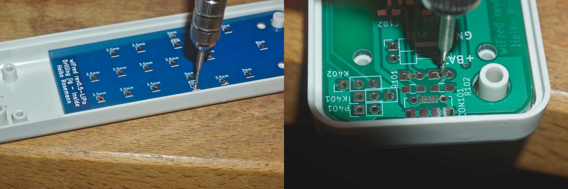
The PCB has holes in the center of the LED footprints to enable transferring their positions to a StrapuBox housing with a sharp needle or to drill pilot holes with a 1 mm drill. For all other holes, there is a drill jig available which also allows the drilling of pilot holes for the pushbutton switches, the direction control switch and the speed potentiometer. Using the original PCB and drilling jig to transfer the positions of the holes to the housing - better results will be achieved when the PCBs are screwed in position shows the process and its results. Holes for the pushbutton switches should be drilled at 3.5 mm diameter. Holes for the LEDs should be drilled at 3 mm diameter and holes for the speed potentiometer at 8 mm, for the direction switch at 6.5 mm diameter. The cutouts for the loco selection switches are best drilled at 1.5 mm and extended to fit when the PCB is assembled with a jigsaw or a sharp hobby knife and a file.
| Designator | Package | Designation |
|---|---|---|
C102, C101 |
C_0805_HandSoldering |
4u7 |
C105, C103, C302 |
C_0805_HandSoldering |
1u |
C206, C205 |
C_0805_HandSoldering |
22p |
C401, C203, C202, C201, C207 |
C_0805_HandSoldering |
100n |
C402, C301 |
C_0805_HandSoldering |
22u |
C403 |
C_0805_HandSoldering |
100u |
CON101 |
USB_Micro-B_Molex-105017-0001 |
USB-MICRO-B |
D101 |
LED_D3.0mm |
LED - red |
D102 |
LED_D3.0mm |
LED - green |
D201 |
SOT-23_Handsoldering |
BAR43 |
D301 |
LED_D3.0mm |
STOP - red |
D302 |
LED_D3.0mm |
FORWARD - green |
D303 |
LED_D3.0mm |
REVERSE - green |
D303, D302, D301, D101, D102 |
LED Spacer |
3mm |
D304 |
LED_D5.0mm_Horicontal_FLIPPED_O1.27mm |
LED white |
D305 |
LED_D5.0mm_Horicontal_O1.27mm |
LED white |
IC101 |
SOT95P270X145-5N |
MCP73831T-2ACI_OT |
IC102 |
SOT95P275X110-5N |
NCV8161BSN300T1G |
IC201 |
TQFP-32_7x7mm_Pitch0.8mm |
ATMEGA328P-A |
IC301 |
SOT-23-6_Handsoldering |
MIC2860-2PYD6 |
K401 |
Pin_Header_Straight_1x03_Pitch2.54mm |
UART_ESP |
K402 |
Pin_Header_Straight_1x03_Pitch2.54mm |
UART_AVR |
P1 |
PCB |
124mm x 35mm x 1.6mm |
P101 |
Pin_Header_Angled_1x02_Pitch2.54mm |
BATT |
P201 |
Pin_Header_Straight_2x03_Pitch2.54mm_SMD |
ISP |
P401 |
Pin_Header_Straight_1x02_Pitch2.54mm |
ESP_BOOTLOAD |
R101, R102 |
C_0805_HandSoldering |
680R |
R103 |
C_0805_HandSoldering |
2k2 |
R301 |
C_0805_HandSoldering |
4k7 |
R304, R303, R302, R204 |
C_0805_HandSoldering |
220R |
R305 |
C_0805_HandSoldering |
15k |
R405, R404, R403, R201, R104 |
C_0805_HandSoldering |
10k |
RV301 |
P160KNPD |
10k lin P160KNPD-4FC20B10K |
SW301 |
OS102011MS2Q |
LOCO1 |
SW302 |
OS102011MS2Q |
LOCO2 |
SW303 |
OS102011MS2Q |
LOCO3 |
SW304 |
OS102011MS2Q |
LOCO4 |
SW305 |
SW_SPST_PTS645 |
F0 |
SW306 |
SW_SPST_PTS645 |
F1 |
SW307 |
SW_SPST_PTS645 |
F2 |
SW308 |
SW_SPST_PTS645 |
F3 |
SW309 |
SW_SPST_PTS645 |
F4 |
SW310 |
SW_SPST_PTS645 |
F5 |
SW311 |
SW_SPST_PTS645 |
SHIFT |
SW312 |
SW_SPST_PTS645 |
ESTOP |
SW313 |
100SP1T1B1M1QEH |
DIRECTION |
SW314 |
SW_SPST_PTS645 |
F6 |
SW315 |
SW_SPST_PTS645 |
F7 |
SW316 |
SW_SPST_PTS645 |
F8 |
U401 |
ESP-12E_SMD |
ESP-12E |
X201 |
Crystal_SMD_TXC_7M-4pin_3.2x2.5mm_HandSoldering |
14.7456MHz |
The remaining assembly is a basic exercise in installing all the components to the PCB, listed in List of components for the wiFred PCB up to revision 0.5. From assembling the prototypes, the suggested order of installing the components is as follows:
-
IC101, IC102, IC201 (note: Rotate PCB so Designator is right side up, then Pin 1 is on top left) and IC301
-
X201 and D201
-
USB connector CON101
-
Capacitors and Resistors in 0805 size (first those on the same side as the items before)
-
U401
-
Capacitors and Resistors not installed before - that is R403, R404, R405, C401, C402 and C403
-
Pushbutton switches SW305 to SW312 and SW314 to SW316 - taking care to place the red one at SW312 and the yellow one at SW311
-
Pin headers K401, K402 and P401 (correct alignment of K401 and K402 can be assured by adding a jumper before soldering)
-
Pin headers P101 and P201
-
Loco selection switches SW301 to SW304
-
LEDs D101, D102 and D301 to D303 with 3mm spacers to the PCB - making sure the Anode (long pin) is aligned with the square pad on all of them
-
LEDs D304 and D305 - making sure the Anode (long pin) is aligned with the square pad on both, they can be installed on top or bottom of the PCB as desired
-
Direction switch SW313 (screwed into the PCB with an 8 mm hex nut first, then attached to it’s pads using the cutoffs from D301, D302 and D303) and Speed potentiometer RV301 (screwed into the PCB with a 10 mm hex nut first)
To form a complete BOM, also include the parts listed in List of components for the wiFred up to revision 0.5 excluding electronic parts to solder to PCB which are not soldered to the PCB but used in assembly later on.
| Designator | Package | Designation |
|---|---|---|
B1 |
Battery |
Lithium battery 1700mAh |
H1a |
Housing black |
Strapubox 2090 |
or H1b |
Housing white |
Strapubox 2090 |
J1, J2 |
Jumper |
|
K1a |
Potentiometer Knob silver |
24mm |
or K1b |
Potentiometer Knob black |
24mm |
P1 |
PCB |
124mm x 35mm x 1.6mm |
S1, S2, S3, S4 |
Mounting Screws |
2,9mm x 6,5mm |
After assembling the PCB with all the components, the holes and cutouts in the enclosure most likely will have to be reworked / extended to actually fit the PCB, then the PCB can be screwed into the enclosure with four screws. Afterwards the battery should be connected to P101 making sure the orientation is correct as shown in Connection of battery to P101 on revision 0.4 - black wire is GND, red wire is positive and printed on the PCB, then the battery should be glued to the bottom of the enclosure with double-sided tape so it does not collide with any parts on the PCB, particularly P101 and SW313. Finally, both the ATMega 328P and the ESP8266 will need to be programmed with firmware as described in Writing the firmware to revision 0.5 and older wiFreds.
Writing the firmware to revision 0.5 and older wiFreds
AVR firmware
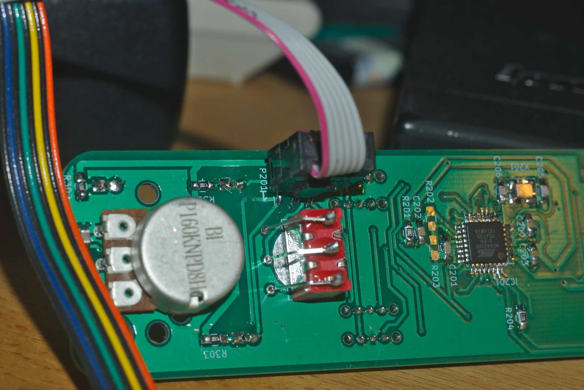
The ATMega 328P is programmed using the regular AVR ISP connection on P201. Pin 1 - GND - is towards the PCB edge, as shown in Programming connection for ATMega_328P - Pin 1 on purple cable. An ISP dongle with either automatic voltage selection or 3.3 V supply voltage should be used to avoid placing too high voltage on the ESP8266, which can only support 3.3 V power. The firmware for the ATMega 328P can be found in the software/avr-firmware-subdirectory of the [Github repository for wiFred] with both a precompiled hexfile and all source code including a Makefile to recompile as needed. After writing the firmware file and the eeprom file, also the fuse bits need to be set properly as detailed in the main.c-file.
ESP8266 firmware
The ESP8266 is programmed using the Arduino IDE connected via a serial or USB-to-serial port to the K401 header as shown in Programming connection for ESP8266 - GND on orange wire, then TXD of programming cable (RXD of ESP8266), then RXD of programming cable (TXD of ESP8266) - also note the jumper on P401. The serial port needs to be at 3.3 V-levels like from an FTDI232-device run at 3.3 V. To program the ESP8266, first the ATMega 328P has to be programmed, a battery has to be connected and reasonably charged and one of the loco selection switches needs to be moved to the "enabled" position to power up the ESP8266.
All files in the software/esp-firmware-subdirectory of the [Github repository for wiFred] need to be placed in a folder, then the main sketch arduino_main_sketch.ino.ino needs to be opened with the Arduino IDE. Settings for the Arduino IDE can be found inside the main file, programming the device should work using the Upload-button in the Sketch-menu.
To put the ESP8266 into programming mode, a jumper needs to be placed across the P401 header before powering up the ESP8266 by enabling one of the loco selection switches to start the device in programming mode. The red STOP LED should start flashing and the bootloader should show some results on the serial port and during download the LED on the ESP8266 module should flash as well.
After programming, two jumpers need to be placed between the K401 and K402 pin headers to re-enable communication between the ESP8266 and the ATMega 328P as shown in Communication jumpers for connecting the ESP8266 and the ATMega 328P.
AA battery first prototype
The wiFred prototype hardware is centered around an ESP8266 for the WiFi connection. The ESP8266 also reads the loco selection switches and the battery voltage and communicates through it’s serial port with an ATMega 328P microcontroller which controls the LEDs, reads the speed potentiometer, direction switch and pushbutton switches for functions and emergency stop. The communication goes through a 2x3 pin header which enables the user to connect a programming cable to the same serial port if removing the jumpers.
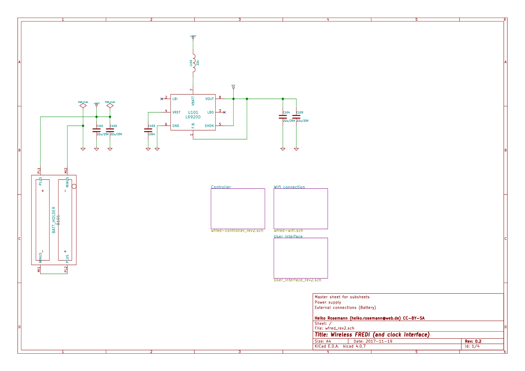
The wiFred prototype is powered by two AA size battery cells connected to a step-up converter creating 3.3 V for the entire device. As soon as a pair of batteries is inserted into the battery compartment as the symbols inside the battery compartment show, the throttle will boot up and try to connect to a wireless network. The throttle will not be damaged if batteries are inserted wrongly, but it will not work either. Use NiMH- or primary AA cells with 1.2 V to 1.5 V nominal voltage, low self discharge NiMH cells like Eneloop or similar are recommended.
The schematic is split into several pages and can be found in Master schematic sheet with batteries and power supply to Schematic sheet including pushbutton switches, loco selection switches, direction switch and speed potentiometer. It has been created with kicad and is available on the [Github repository for wiFred] along with the PCB design.
Hints for building the wiFred AA battery prototype
The prototype PCB has holes in the center of the pushbutton switch footprints and LED footprints to enable transferring their positions to a StrapuBox housing with a sharp needle or similar, and the position of the loco selection switches can also be transferred to the housing by marking it through the non-copper holes at their ends. Refer to Hints for building revisions up to 0.5 for pictures and more detail, the differences between the AA battery prototype and the LiPo battery revisions are minimal in this aspect.
The remaining assembly is a basic exercise in installing all the components to the PCB, listed in List of components for the AA battery prototype wiFred.
| Designator | Package | Designation |
|---|---|---|
B101 |
KEYSTONE1013 |
BATT_HOLDER |
C206, C205 |
C_0805_HandSoldering |
22p |
C301, C105, C104, C102, C101, C402 |
C_0805_HandSoldering |
22u |
C401, C204, C203, C202, C201, C103 |
C_0805_HandSoldering |
100n |
D301 |
LED_D3.0mm |
STOP - red |
D302 |
LED_D3.0mm |
FORWARD - green |
D303 |
LED_D3.0mm |
REVERSE - green |
IC201 |
TQFP-32_7x7mm_Pitch0.8mm |
ATMEGA328P-A |
K401 |
Pin_Header_Straight_1x03_Pitch2.54mm |
UART_ESP |
K402 |
Pin_Header_Straight_1x03_Pitch2.54mm |
UART_AVR |
L101 |
L_2424_HandSoldering |
22u |
P201 |
Pin_Header_Straight_2x03_Pitch2.54mm_SMD |
ISP |
P401 |
Pin_Header_Straight_1x02_Pitch2.54mm |
ESP_BOOTLOAD |
R301 |
C_0805_HandSoldering |
4k7 |
R304, R303, R302 |
C_0805_HandSoldering |
470R |
R401 |
C_0805_HandSoldering |
100k |
R402 |
C_0805_HandSoldering |
47k |
R405, R404, R403, R201 |
C_0805_HandSoldering |
10k |
RV301 |
P160KNPD |
10k lin P160KNPD-4FC20B10K |
SW301 |
OS102011MS2Q |
LOCO1 |
SW302 |
OS102011MS2Q |
LOCO2 |
SW303 |
OS102011MS2Q |
LOCO3 |
SW304 |
OS102011MS2Q |
LOCO4 |
SW305 |
KSC621G |
F0 |
SW306 |
KSC621G |
F1 |
SW307 |
KSC621G |
F2 |
SW308 |
KSC621G |
F3 |
SW309 |
KSC621G |
F4 |
SW310 |
KSC621G |
SHIFT2 |
SW311 |
KSC621G |
SHIFT |
SW312 |
KSC621G |
ESTOP |
SW313 |
100SP1T1B1M1QEH |
DIRECTION |
U101 |
TSSOP-8_4.4x3mm_Pitch0.65mm |
L6920D |
U401 |
ESP-12E_SMD |
ESP-12E |
X201 |
Crystal_SMD_TXC_7M-4pin_3.2x2.5mm_HandSoldering |
14.7456MHz |
Housing StrapuBox 6090 |
||
Two Jumpers, 2.54mm |
||
Potentiometer Knob, 21 mm |
||
Three fastening screws, 2.9 mm dia x 6.5 mm |
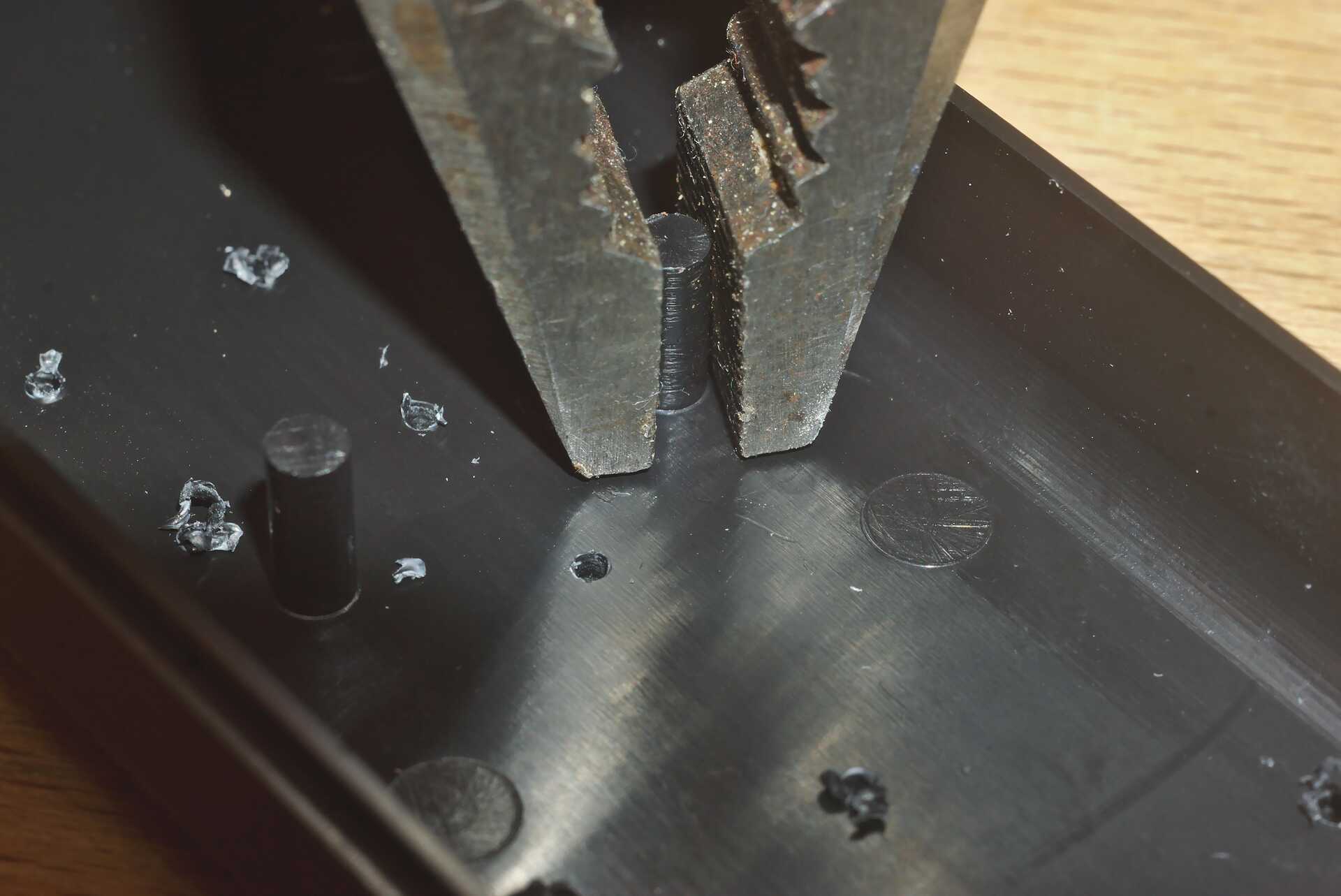
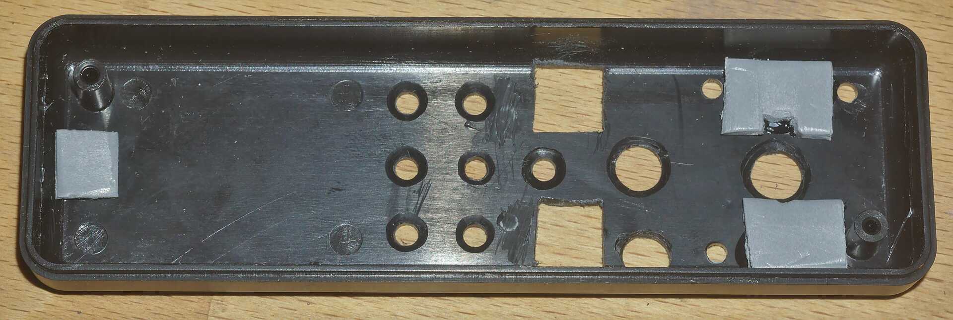
After assembling the PCB with all the components and drilling and cutting the holes and cutouts into the housing, there are few steps left. First, a few protrusions inside the housing need to be removed so the PCB fits properly. Removing protrusions inside the housing so the PCB fits shows how they can be removed easily, remains may be cut off with a hobby knife. Second, new PCB mounting pads need to be installed as shown in New PCB mounting pads made from 3 mm thick Forex PVC. For the prototype, Forex PVC foam was used, cut with a pair of scissors and glued to the housing with superglue, making sure not to be in the way of any components on the PCB, but any kind of easily worked upon material with a thickness of 3 mm can be used, as long as it will take self-driving screws (prototype uses 2.9 mm by 6.5 mm DIN 7981 screws). Third, the two shift keys need yellow paint on the top and the emergency stop key needs red paint - either any kind of paint or a paint marker like Edding 751 will do. Finally, both the ESP8266 and the ATMega 328P will need to be programmed as described in Writing the firmware to revision 0.5 and older wiFreds.
Background for wiFred development
As of the writing of this document, [JMRI] has a long track record of offering a server for using smartphones as wireless model railroad throttles, along with apps like [wiThrottle][10] and [EngineDriver]. This server will enable WiFi throttles to control locos any model railroading layout to which JMRI can build a connection [Supported Hardware]. In addition, [Digitrax LNWI] and [MRC Prodigy WiFi] offer specific hardware solutions to enable the connection of the abovementioned smartphone apps to their DCC systems through a WiFi network.
The [Fremo] is a European modular model railroading club whose unique requirements on its DCC throttles led to the creation of the throttles [FRED] and [FREDI] - a series of LocoNet-throttles which started their life as hobbyist projects with large numbers in circulation but were also commercially available from [Uhlenbrock].
Specification wishlist
In modular railroading events, particularly of the Fremo-americaN-group, multiple people have evaluated the smartphone throttle solutions and found them lacking a nice, haptical feedback. But the idea of wireless control without locking into a specific vendor and their necessarily expensive equipment found great approval. So a wishlist was compiled to define the requirements for a wireless throttle:
-
Same form factor as the [FRED] with similar controls
-
Option to control at least two, better four locomotives for double/triple traction (similar to the double FRED)
-
Battery runtime of at least six hours
-
Exchangeable batteries, so when the battery runs down, they can be quickly exchanged for a charged set or cheap primary cells
-
Easy configuration, but not too easy to prevent operators from accidentally selecting other locomotives
-
As little change to the existing Fremo Loconet network as possible
-
Use of wiThrottle protocol, so the server side of the communication can be assumed to work and does not have to be developed as well
Development history
The first prototype versions of the wiFred were built to run from two AA cells, either dry batteries or rechargeable NiMH cells. As described in AA battery first prototype this required some special adaptations of the housing to fit all components. Even then, experience with the prototypes showed the battery compartment cover did not really fit and easily broke when trying to open and close the battery compartment.
So the next versions were built around an integrated lithium battery, losing the ability to exchange empty batteries, but with increased runtime and proper fit into the housing. Recharging of the second generation is done through a Micro USB connector, so a powerbank can extend the runtime of the device when the internal battery is exhausted. Also, the loco selection switches act as more of a power switch than they did with the first prototypes, reducing power consumption to a negligible amount when all locos are deselected.
The latest prototype will switch from a double processor implementation to a single, new ESP32-S2 processor, saving space, reducing the number of components, placing all SMD components on one side of the PCB and enabling direct USB firmware download. It will not contain any new features over the earlier LiPo battery versions, but mainly be easier to build for the hobbyist.
Wireless clock
During the development of this wiFred another topic came up in the americaN group of the Fremo, namely wireless clocks with adjustable clock rate for Timetable & Trainorder operations. This led to the spinoff of the [wiClock] project.
References
-
[Github repository for wiFred] newHeiko/wiFred: wiThrottle-compatible hardware controller, https://github.com/newHeiko/wiFred
-
[JMRI] JMRI: A Java Model Railroad Interface, https://www.jmri.org
-
[Supported Hardware] JMRI: Hardware Support, https://www.jmri.org/help/en/html/hardware/index.shtml
-
[wiThrottle] WiThrottle, https://www.withrottle.com/html/home.html
-
[EngineDriver] Home | EngineDriver, https://enginedriver.mstevetodd.com/
-
[Fremo] Home - FREMO - Freundeskreis Europäischer Modelleisenbahner e.V., https://www.fremo-net.eu/en/home/
-
[FRED] FRED, http://fremodcc.sourceforge.net/diy/fred/fred_e.html
-
[FREDI] FREDI, http://fremodcc.sourceforge.net/diy/fred2/fredi_d.html (German only)
-
[Uhlenbrock] Uhlenbrock | FRED, der Handregler für die Intellibox, https://uhlenbrock.de/de_DE/produkte/prodarch/I62AD172-001.htm!ArcEntryInfo=0004.41.I62AD172
-
[Digitrax LNWI] LocoNet WiFi interface, https://www.digitrax.com/products/wireless/lnwi/
-
[MRC Prodigy WiFi] Prodigy WiFi, https://www.modelrectifier.com/Prodigy-WiFi-s/332.htm
-
[Steve Todd] JMRI RaspberryPi as Access Point | M Steve Todd, https://mstevetodd.com/rpi
-
[wiClock] wiClock, a WiFi-JMRI-Clock, found at https://github.com/newHeiko/WiFi-JMRI-Clock or its documentation at https://newHeiko.github.io/WiFi-JMRI-Clock