Intensive use of the wiFred of revisions 0.5 and 0.51 revealed a mistake in the way the LEDs and key switches are connected to the AVR on PCBs with rev0.5 and rev0.51: In certain situations, pressing one function key will be read as multiple key presses. This is most obvious with F2, F5 or F8 also activating ESTOP. This document describes a fix which has been implemented successfully in many wiFreds and also incorporated into the rev0.52 PCB and schematic. It removes the LEDs from the key read-in matrix.
Tools and parts needed
This work requires some solder wick, a total of three 220-Ohm THT resistors of size 0207 (the usual 0.25W carbon film or 0.6W metal film types are fine) and some length of heat-shrink tube of about 2.4mm diameter.
To update the firmware, an AVR programmer for the regular AVR ISP connector P201 on the PCB is required.
How to fix, step by step
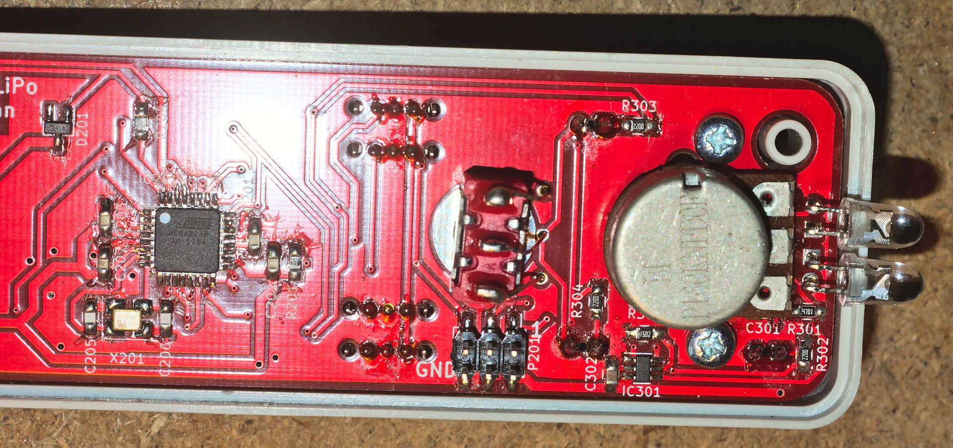
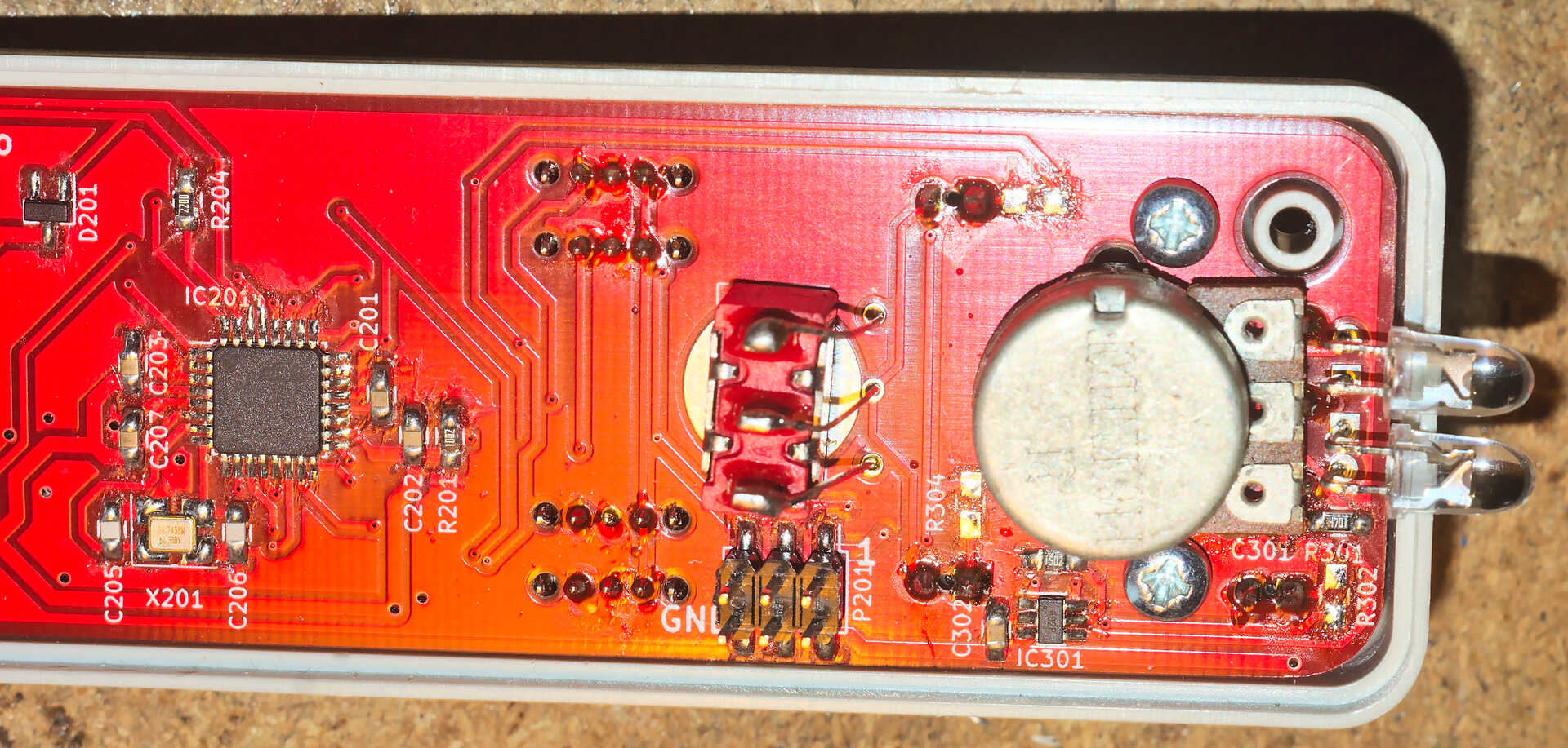
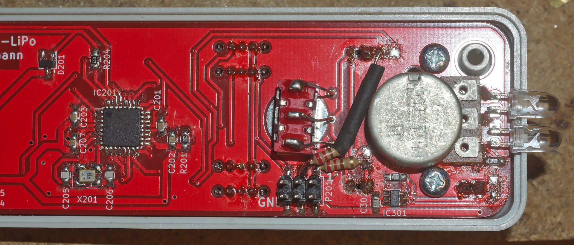
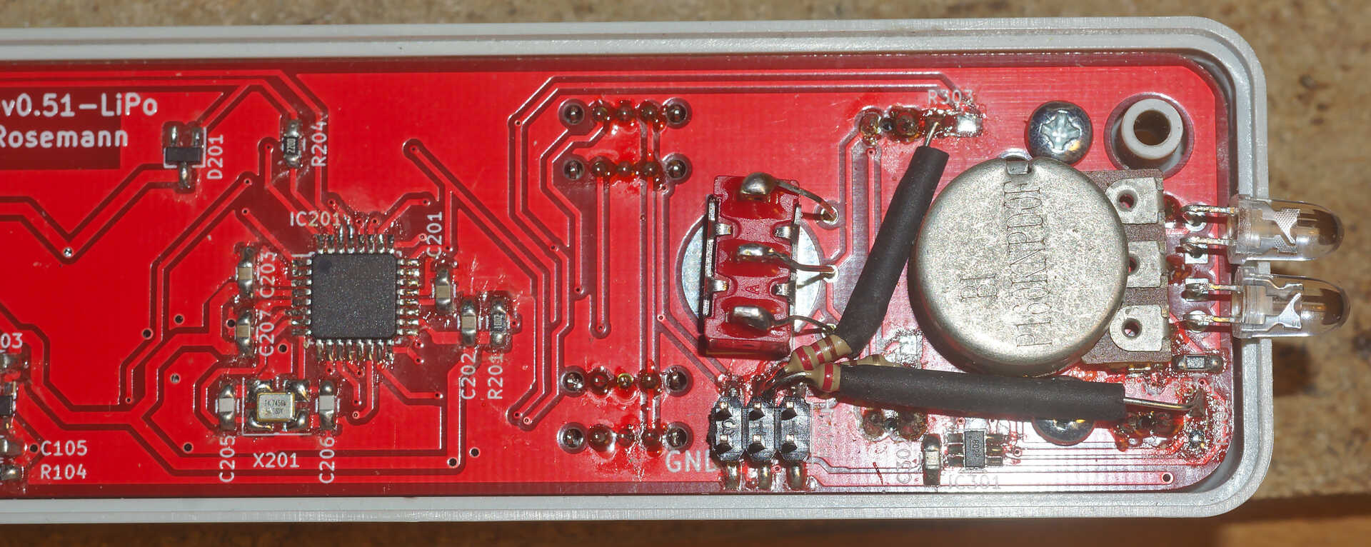
First, remove the SMD resistors R302, R303 and R304 as shown in PCB rev0.51 showing the half with resistors R302, R303 and R304 to be removed and PCB rev0.51 after removal of R302, R303 and R304 and clean their pads with some solder wick.
Next, get the first of the 220-Ohm THT resistors (size 0207), cut and bend the leads very short so it connects Pin 1 of P201 to the outer pad of former R304 and solder it as shown in PCB rev0.51 with the first of three replacement resistors installed.
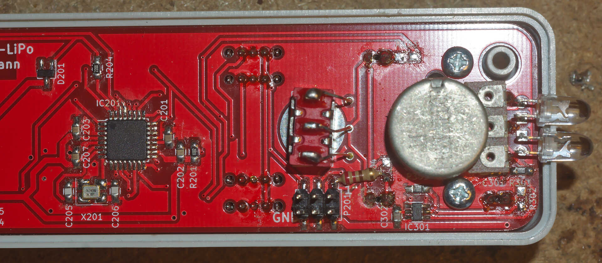
The second 220-Ohm THT resistors needs a little more shaping of its leads. It should connect pin 3 of P201 (center pin in the upper row) with the inner, left pad of former R303, as shown in PCB rev0.51 with the second of three replacement resistors test-fit, but not yet soldered. As the longer lead of that resistor passes close to a couple of metal pieces in the wiFred, it is recommended to cut a piece of heat-shrink tube and fit it over the bare metal of the lead, as shown in PCB rev0.51 with the second of three replacement resistors soldered after covering the bare lead with heat-shrink tube. It is not required to actually shrink it as it will be held in place by the resistor and the solder point.
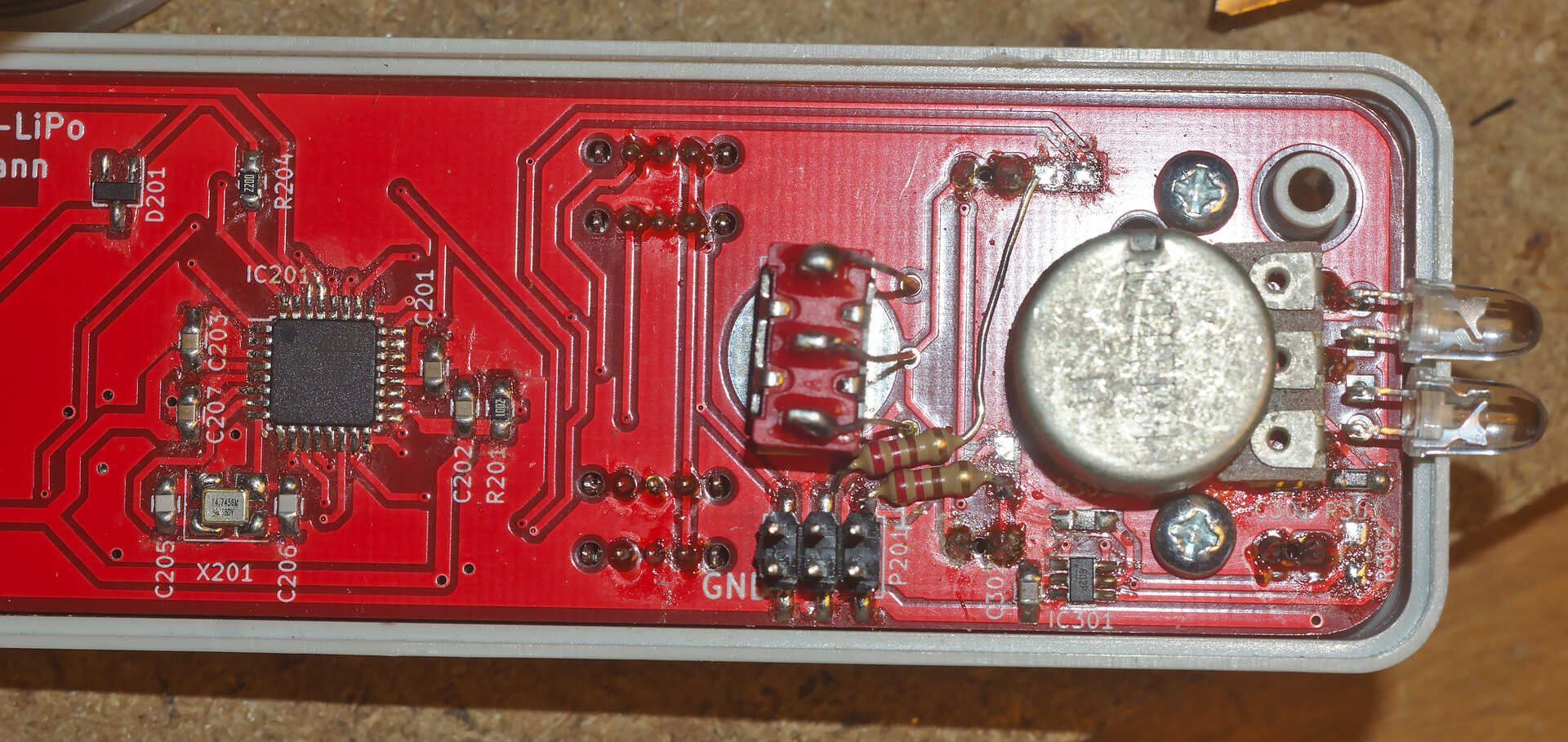
The final 220-Ohm THT resistor is installed in a similar fashion to the second one, also attaching to pin 3 of P201 and connecting it to the center (upper) pad of former R302 as shown in PCB rev0.51 with all three replacement resistors installed. It also has a long bare lead floating close to other metal parts, so insulation with heat-shrink tube is recommended. Also it blocks access to the lower right (in the picture) screw attaching the PCB to the housing, so either bend it a little different from the picture, remove the screw or make sure access to the top side of the PCB is not required.
Software required
To make the LEDs light up with their new connections, a new AVR firmware is required. It is distributed through the github repository and dated 2025-03-26.
Before updating the AVR firmware, it is recommended to update the ESP12 firmware through the web interface of the wiFred. As of this writing, any firmware with -esp12.bin in the filename should work, starting from 2022-10-16-ff2c954-esp12.bin.